Select Similar Objects / Blocks / Components

Learn how to select all the instances of a component
Català - Castellano - Deutsch
I post often how to find ways to mimic behavior of different programs. We get used to certain tricks that make us work fast and then we miss those things when using a different software.
This is the case of the AutoCAD Architecture function "Select Similar". What this does is to select all instances of an object with the same properties. For instance, if we select a wall, right click and choose "select similar" in the context menu, all the walls of the same style on the objects layer will be selected. The same happens with any object sharing properties and layer with the selected objects.


So how do we do this in SketchUp? There is actually not one method that does all this, but there are several ways to achieve a similar result. If what we want is to select all the instances of a component (the equivalent to Blocks in SketchUp) we need to open the component browser (Window --> Components), then right click the thumbnail of the component we want to select and choose Select Instances (we already went through this on a previous post about How to Replace all instances of a Component).
If what we want is to select all the objects on a Layer, we can simply select one object that lays on that layer, right click it and go to Select --> All on same Layer.

These tricks on SketchUp don't do exaclty the same as the very useful "select similar" command of AutoCAD Architecture and the other AEC versions of AutoCAD, but they are close enough.

Show me more...

SketchUp Plugins: How to Draw a Helix or a Spiral

Easiy draw helixes or spiral curves with this simple plugin.
Català - Castellano - Deutsch
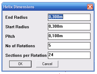
DRAW HELIX (drawhelix13.rb) by Peter Brown allows us to draw helix and spiral curves (flat helix). It is very easy to use and quick. It is accessible via Draw --> Helix (I've modified slightly the original code that was pointing to Draw --> DrawHelix13). It shows a dilog box like the following one, where you can set the different options.


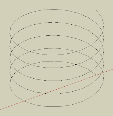
Pitch is the Height of one Helix Rotation. That way, if we set the pitch to 1m and number of rotations to 5, the total heght of the helix will be 5m. The number of segments per rotations will define how many lne segments will form each rotation. This is the result obtained with the default values shown on the image above.


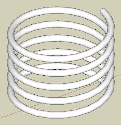
By using a plugin like TUBE ALONG PATH, we are able to turn the helix line generated to a rederable helix.


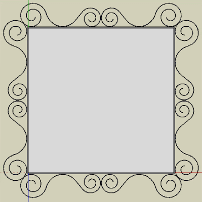
If we want to draw spirals (a flat helix of changing radius) we simply need to set the Pitch to 0. See how I modeled my ugly living room mirror ;).


Chek here how to Install SketchUp Plugins.


Show me more...
Maxwell Render: New 2.0 Version Coming Soon

Check out the new features of the upcoming version 2.0 of Maxwell Render.
Català - Castellano - Deutsch
Next Limit is announcing on their website the new features of the soon to be released Maxwell render Version 2. The website has plenty of examples of the improved features comparing them to the latest released version v1.7.
So far, for what I've seen on the website, the speed improvement (one of the weak points of Maxwell has always been speed) is amazing, and the behavior of light sources has also been tremendously improved.
I can't wait for the release of this new version and find out about all the new features.


Show me more...

AutoCAD: Use Curved Frames to Clip your References

Clip your Blocks or XREFs using curved polylines, circles, etc
Català - Castellano - Deutsch
A common problem found when using the XCLIP command is that it doesn't clip properly if the polyline we use has curved segments. The same way we can't use circles to clip Blocks or XREFs. If you try to clip a block using a polyline that contains curved segments you will see that along the curved segment the clipping is not done properly. See the following image. The block was clipped using the yellow polyline. The result is not satisfactory at all.


The first image shows the original block, the second one is the block clipped with the XCLIP command. As you see we need a work around this result. The work around is to use an Express Tool Command.

CLIPIT is an express tool command that will allow us to do what we wanted to do. CLIPIT will ask us to select the new clipping frame, that can actually be a POLYLINE, CIRCLE, ARC, ELLIPSE, or TEXT object. It works the opposite as the XCLIP command. With CLIPIT you first select the frame and then the Block, Image, Wipeout or XREF you want to clip. See the following image with the result.


What CLIPIT does, is turn the curved clipping frame into a set of segments. If you switch on the XCLIPFRAME and select the block, you will see that the frame is actually made of straight lines. See it below.


The only bad part of this express tool, is that so far (till version 2009) it doesn't allow inverted clips. We talked about how useful inverted XCLIPS can be on a previous post. Hopefully in future versions of AutoCAD this will be solved.

Show me more...

AutoCAD: Select all Connected Geometry.

Wonder how to select with a single click all connected geometry? AutoCAD can do it, you just need to know the right command.
Català - Castellano - Deutsch
Usually my day at work involves designing and drawing both in AutoCAD and SketchUp (and eventually in Rhino depending on the complexity of the geometry of the project). Switching back and forth from one software to another makes you miss on one program some of the functions that the other program has. This was the case of the "Select all Connected" option in SketchUp. It is so useful to select all connected geometry (it can be accessed through a right click menu or by triple clicking any line on the drawing). But can something similar be done in AutoCAD? The answer is yes.

There is an Express Tool for AutoCAD called FASTSEL (accessible also via the FS shortcut) that allows us to select all the geometry that is connected (touching) any element on our drawing. The elements that can be used using this commands are LINE, POLYLINE, LWPOLYLINE, CIRCLE, ARC, ATTDEF, TEXT, MTEXT, ELLIPSE, SPLINE or IMAGE objects. BLOCKS or XREFs containing these objects will also work.
AEC Objects from some of the vertical products such as Walls or AEC Polygons are not supported. In case you have a Block or XREF containing both supported and unsupported elements, the command will only use the supported elements.

The command can be accessed transparently while using other commands by typing 'FS while the command is running. Also, use the FSMODE System Variable to control if the FS command selects all connected geometry (FSMODE = ON) or only the geometry connected to the first object (FSMODE = OFF).

Note that this Express Tool Command is mostly intended for 2D since I tried to use it in 3D and lines that are actually not touching other geometry did get connected. I find it specially useful when I accidentally explode polylines, with this command you can select all the lines that where previously connected with a single click. Select faster than a private jet with this express tool!

Show me more...

SketchUp Plugins: Slice Your Model

Do you need to get slices of your SketchUp model to build a real life model? Slice it easily with this Plugin.
Català - Castellano - Deutsch
A common process in my office is to design some of the buildings in SketchUp and then build physical models of them cutting the pieces with a laser machine. With simple geometry this is no problem, and it is easy to draw the outlines of the pieces in AutoCAD to send them to the laser cutter. When the Gemoetry is more complex the process requires a bit more effort.

SLICER (slicer.rb)
is a Plugin that helps doing this. The Plugin generates slices from a given 3D model and you can choose which axis you want to use for the slices to be generated.
See the following example. I used the same terrain I used on a previous post and I created slices of it every 5m.


The plugin even asks you if you want a flattened copy of your slices, which basically means that it will spread the slices on the ground plane, so you can just set a Top view and Export to AutoCAD. See the image of this other simpler model.


Of course CAD exports from SketchUp are not always very clean, so there might be some tweaking needed before using a laser cutter, but this definitely speeds up the process. To use the plugin, select a Group or Component, go to Plugins --> Slicer and then use the dialog box to configure how the slices should be created. Download the Plugin here.

Chek here how to Install SketchUp Plugins.


Show me more...

AutoCAD: Delete a Layer that Contains Objects

Do you need to delete a layer but the purge command doesn't do it? No worries, there is an express tool for that.
Català - Castellano - Deutsch
One more day of problem solving at work. Ryan asked me today if I knew how to delete a layer that the purge command doesn't delete. The solution is to use one of the Layer Express Tools. And of course I thought: let's write about it here during my lunch break! It is raining anyways.

LAYDEL is an Express Tools Command that allows us to delete a layer even if it contains objects. This is useful to delete layers we want to purge but because they might be included in some block definition we are not using anymore, the purge command can't delete them. Be careful though, since it will delete the layer and its contents. TO use it simply make sure that the layer you want to delete is not current, type LAYDEL and select an object on that layer (alternatively you can access this function through Format --> Layer Tools --> Layer Delete).

There is an alternative method to delete a layer but keep its objects. The LAYMRG Express Tool Command merges one layer into another and deletes the first one. It is very useful when trying to simplify the layer structure of a drawing but we want to keep all its graphical information. To use it, type LAYMRG (alternatively you can access this function through Format --> Layer Tools --> Layer Merge)select the layer to delete and merge, press ENTER, then select the target layer where you want the information to be merged to.

Show me more...

SketchUp: Load new Plugins without Restarting the Program

Do you want to load a new Plugin without restarting SketchUp? Alex Schreyer has a Plugin for that.
Català - Castellano - Deutsch
Sometimes we want to try new Plugins we just downloaded without the "hassle" of closing SketchUp and opening it againg. Alex Schreyer, has written a Ruby Script that allows us to do that.
PLUGIN LOADER (as_pluginloader.rb) adds a submenu to the plugin menu that allows us to reload the entire Plugins folder or to pick one by one which Plugins we want to load.


You can download the plugin using the above link or go to Alex Schreyer Website were he keeps updating it with the latest release.

Show me more...

AutoCAD: Offset Ellipses and keep them as Ellipses

Tired of getting SPLINES when you offset you ellipses? Maybe you want to try this quick video tutorial.
Català - Castellano - Deutsch
One of the biggest issues of working with ellipses is the fact that if we offset them using the OFFSET command, they become Splines. Splines are entities that are hard to work with, especially when we need to trim parts and later we want to extend them again. Tired of toggling the PELLISPE system variable many times, i wanted to see if there was a way to offset an ellipse but keep it as an ellipse. I did found the way to do it. It is a bit slower than using the OFFSET command, but if you think you might need to edit the resulting ellipse maybe you want to give it a try. See the video below.


The steps are simple:
  1. Draw two lines from the quadrants of the ellipse. Their length should be the distance you want to offset the ellipse. (To be able to Snap on the qadrants, turn them or access the quadrant osnap with through the OSNAP contextual menu)
  2. Select the ellipse, move one of the grips next to one of the lines to the other end point of that line while holding the CTRL key.
  3. Move the grip next to the other line you previously draw to the other endpoint of the line
That´s it, your resulting parallel ellipse is still an ellipse and not a SPLINE.


Show me more...

SketchUp Plugins: Color Terrain to Show Terrain Slope or Height

Need to see which are the high points of your terrain or which areas are too steep to build on? Use thses next two plugins to quickly see that.
Català - Castellano - Deutsch
Chris Fullmer published some time ago a couple of plugins to Color Models according to the Height or the Angle of the faces. This turns to be very useful in many situations. I came across these Plugins because we were planning a new development and needed to easily visualize in plan which where the high points and were we had too steep areas.

COLOR BY Z (clf_color_by_z): Colors faces according to their height (z value). you can pick which color you want to be the one for the highest point, and which one you want for the lowest point. It will create a gradient from one color to the other. See the images below.


COLOR BY SLOPE (clf_color_by_slope): Does the same trick, but coloring the faces according to its angle (slope).


See these next two Plan shots to understand how this could be useful to you to identify potentially bad areas to build or to simply glimpse the height changes of your terrain in plan.


Show me more...

Autodesk Announces Support for MAC Boot Camp Users

One step closer to be able to use AutoCAD on your Mac 100% hassle free.
Català - Castellano - Deutsch
Autodesk has a website were it announces support for Boot Camp Mac users. This doesn't mean you will be able to run AutoCAD on your MAC OS, you still need bootcamp, but at least now Autodesk is making sure AutoCAD (and other products such as 3Dmax, Inventor and Revit) run properly on Boot Camp. I can't tell if the rumors of a deal between Autodesk and Apple to have a MAC version of AutoCAD are true (I've read numerous posts about it) but at least this is little step forward.

Show me more...

SketchUp: How to Install Plugins

What you need to know to install and find Google SketchUp Plugins
Català - Castellano - Deutsch
SketchUp Plugins, also referred to as Ruby Scripts, are pieces of Ruby code intended to extend the functionality of SketchUp. How to install SketchUp Plugins ? You simply need to copy them into the Plugins Folder of SketchUp and restart the program (or use the Plugin loader as-pluginloader.rb). By default the plugins folder is located under

C:\Program Files\Google\Google SketchUp 7\Plugins. (Windows)
or
Macintosh HD/Library/Application Support/Google SketchUp 7/SketchUp/ (Mac)

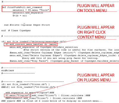
Once you've done this, the plugin will appear in one of the menus. Be sure to check both the Plugins Menu, and the Tools menu. Many developers prefer to put their plugins into the Tools menu instead of Plugins, this is the case for plugins such as Joint Push Pull, Make Faces, and many others. So be sure that you check all the menus because the new feature might be in some other menu that is not the Plugins menu. There are even some plugins that end up on the View menu, like PageExIm.rb and some others.

If you want to be sure of which Menu the plugin should appear in, you can open the .rb script file and check its description. Many developers include in the beginning of the script some comments that explain how to use or where to find the script. If those comments are missing, scroll down to the bottom of the code and you will find a string of code like these ones.


Show me more...

AutoCAD: Use the autosave files to recover your work

Make sure you activate the autosave option and see where to recover the files from.
Català - Castellano - Deutsch
We had an awful day at work today with lots of FATAL ERROR crashes, probably due to some circular references on the XREFs. Some of the files ended up being completely unrecoverable so we had to find the most updated backup files we could find. This made me write an e-mail to everyone explaining how to find and use the backup files that are created with the auto save option in AutoCAD.

Although for "light" crashes, these files can be accessed through the recovery wizard, this was not our case, so it was a question of searching and finding those auto-save files to replace the corrupted ones. I thought I'd share here that information in case someone doesn't know about the auto-save feature and how o locate those files.

1. Go to Tools --> Options
2. Inside Options go to the “Files” Tab (far left)
3. Inside the files tab go to: “Automatic Save File Location” and see where the autosave files are stored. (mine where stored at C:\Documents and Settings\USERNAME\Local Settings\Temp)
4. Then access that folder and try to find a file with the same file name but different extension. (The autosave files should have a either a .BAK or a .SV$ extension) (if you can’t see the folder, you need to go to Tools --> folder Options --> View --> and Make sure "show hidden files and folders" is SELECTED) .
5. Check the "date modified" of those files, if the date and time makes sense according to when you had the last file crshes, there is a good chance that those files contain the information you need, so there is no need to redraw everything.
6. Change the file extension of the file you think it might be the good one from .bak or .sv$ to .dwg (to be able to change the file extension you need to be able to see it. To do that, on any folder go to Tools --> Folder Options --> View --> and make sure that "Hide extensions for known file types" is UNCHECKED)

If your auto-save feature is disabled, you can enable it in AutoCAD by going to Tools --> Options --> "Open and Save" Tab --> and there make sure that the "Automatic save" on the lower left corner is active and preferably set to every 10 minutes or less. To easily change the time of the autosave feature, use the SAVETIME system variable (this last tip thanks to lazydrafter)

Hope this helps, it saved me 2 hours of work. Using it properly is like having good car insurance. You never know when you'll need it!

Show me more...
SketchUp Plugins: Turn Lines into Tubes / Cylinders

Turn lines into cylinders with one of these two Plugins.
Català - Castellano - Deutsch
There might be several reasons why you want to turn your lines into cylinders/tubes. You might just want to be able to render a bunch of lines in your model. In that case, you need to turn them into cylinders or else they will not appear on renderings. You have two plugins to do this.

LINES TO TUBES (lines2tubes.rb): by Didier. Formerly known as LINE TO CYLINDERS (lin2cyl.rb)Will turn a bunch of lines, arcs, circles, curves, etc into cylinders of a given diameter. It doesn't matter if they are connected, just select the linework, go to Tools --> "Convert circles, arcs, curves, lines to cylinders". Download it here.The advantage is that you can simply select all the linework and convert it to pipes, the disadvantage is that all the corners between different entities will not have Follow Me connections, just pure Push Pull.


TUBE ALONG PATH (TubeAlongPath.rb): by TIG. Does the same operation but only for connected paths. It has the advantage of automatically creating follow me operations when reaching corners of the path. The disadvantage is that only connected paths can be created at once. To use it select the lines that create the path, go to Plugins --> Tube Along Path. Download it here.


Show me more...

SketchUp Plugins: Fill the Section Cut With a Face

Fill the section cut with a face for better display with the sectioncutface plugin
Català - Castellano - Deutsch
TIG has published an updated version of his SectionCutFace.rb plugin (version 2.2). THis plugin adds a face to fill the section created with the standard SketchUp tool "Section Plane".

For those newbies who don't know "Section Plane", it is a standard tool (under the Tools menu --> Section Plane) that allows you to automatically cut a section trough your model. See it graphically.


What TIG's plugins adds is the feature to select the section plane, right click it and select Add Section-Cut Face. This (if you have a clean model) will generate the face for the section cut, like in the image below.


The Plugin has a dialog where you can play with several of the options, and that looks like this.


To be able to run the plugin, you need to have the section plane active. To do so go to the Menu View --> Section Planes (it has to be checked so you see it on the screen so you can right click on it).

You can Download the Plugin here.

If you are new to SketchUp chek here to know how to Install SketchUp Plugins

Show me more...
SketchUp: List of Plugins

Find here all the SketchUp Plugins that have been listed on CAD-Addict.com
Català - Castellano - Deutsch
This is the up to date, list of all the SketchUp Plugins I´ve talked about in CAD-Addict.com (it will be updated in the future as soon as new Plugins are added as new posts)
  1. ARTMINE: Allows you to import more than 5000 pieces of art to your sketchup model
  2. BEZIER (bezier.rb): creates Bezier curves
  3. CADSPAN: Makes your model 3D print ready and exports to STL format.
  4. CAMERA RECORDER (clf_camera_recorder.zip): Records your camera movements and exports a set of images to be able to create a walkthrough animation.
  5. CLEANUP (tt_cleanup.rb): excellent Plugin to clean geometry, unnecessary coplanar edges and other features.
  6. COLOR BY SLOPE (clf_color-by_slope.rb): Colors faces according to their angle
  7. COLOR BY Z (clf_color_by_z.rb): Colors Faces according to their Z value (height)
  8. COMPONENT STRINGER (clf_component_stringer.rb): Places components along a path, with several options of scaling and rotation.
  9. CUBIC PANO OUT (cubicpanoout.rb): exports 6 images to generate a 360 degrees quicktime panorama.
  10. DELETE COPLANAR EDGES (deletecoplanaredges.rb): Removes unnecessary edges between coplanar faces.
  11. DROP (drop.rb): Drops groups/components till they intersect with the model, ideal for site modeling.
  12. ELLIPSE ( rp_ellipse_v12.rb): Allows you to draw ellipses
  13. ENGINEERING TOOLBOX (EngineeringToolbox.rb): Allows you to place standard beams, ducts, elbows, etc.
  14. EXTRAPOLATE COLORS (lf_extrapolate_colors.rb):paints a bunch of faces randomly allowing you control on the colors used.
  15. EXTRUDE EDGES BY EDGES (extrudeEdgesByEdges.rb): to extrude a curved edge along a curved path.
  16. EXTRUDE EDGES BY FACE (ExtrudeEdgesByFace.rb): An easie to use follow me Tool. Extrude a face along a path without the need to align that face with it.
  17. EXTRUDE EDGES WITH ROTATION (ExtrudeEdgesByLathe.rb): Extrudes rotationg the edges or the face a certain angle around a given axis.
  18. EXTRUDE EDGES BY RAILS (extrudeEdgesByRails.rb): Extrudes an edge following to given rails.
  19. EXTRUDE LINES (extrudelintool.rb): extrudes lines using a vector.
  20. FLATTERY (flattery.rb): An upgraded unfold tool, to turn your 3D model into a 2D unfolded model ready to be cut in paper and glued together.
  21. FLIGHT PATH (flightpath.rb): Allows to generate the scenes of a flythrough animation by selecting a path.
  22. FREE SCALE (FreeScale_Tool.rb): Aligns the Scale Box to any line on the drawing.
  23. GEOMETRIC CURVE SMOOTHING (crvsmth.rb): Edit Curves
  24. GREEBLE 2 (clf_greeble_2.rb): Allows you to add random, and not so random, complexity to your geometry.
  25. GRIDS (grid.rb): to create parametric grids.
  26. HELIX (drawhelix13.rb): Draws a helix or a spiral
  27. HOVER SELECT (HoverSelect.rb): Select or deselect edges by click and drag.
  28. INSTANT ROAD (InstantRoad.rbs): Creates roads quick and easy
  29. INSTANT ROOF (InstantRoof.rbs): Creates pitched roofs with just a few clicks
  30. JOINT PUSH PULL (JointPushPull.rb): Allows you to Push Curved Faces.
  31. LATICEIZER (Laticeizer.rb): creates a window with its mullions and glass parts from a series of faces, cleaning up the intersections very neatly
  32. LINES TO TUBES (lines2tubes.rb): turn a bunch of lines, arcs, circles, curves, etc into cylinders.
  33. LOFT (clf_simple_loft.rb): Creates a simple loft between two or more profiles.
  34. MAKE FACES (makefaces.rb): Generates all possible faces from selected geometry.
  35. XD MAKE FUR (fur_en_v1_2.rb): A Plugin to generate Fur / Grass with a lot of control.
  36. MIRROR (mirror.rb): Mirror objects selecting a mirror plane.
  37. MODELFUNCTION (Modelfunction.exe): Sort of explicit history (primitive grasshopper) for SketchUp, very promising
  38. OFFSET ON SURFACE (OffsetOnSurface.rb): Allows you to offset curved faces.
  39. ONION DOME (oniondome.rb): to create onion shaped domes.
  40. ONTIME 5D (ontime5d.rbs): easily simulate the construction process (virtual scheduling or 4D modelling) for free.
  41. PAGE EXPORT IMPORT (PageExIm.rb): Allows you to export pages to be imported to another model.(not free)
  42. PLUGIN LOADER (as_pluginloader.rb): Loads plugins without restarting SketchUp.
  43. ROTATED RECTANGLE (rectangle.rb): creates rotated rectangles.
  44. ROUND CORNERS (RoundCorner_Tool.rb): Turns sharp corners into round ones.
  45. SCALE ROTATE MULTIPLE (clf_scale_rotate_multiple.rb): Randomly Scale and rotate objects, ideal for Vegetation / Site Design.
  46. SECTION CUT FACE (SectionCutFace.rb): Fills the section cut with a face.
  47. SELECTION HIDE/SHOW (SelectionHideShow.rb): Adds contextual menu options to show hide selections in many different ways.
  48. SHAPE BENDER (clf_shape_bender.rb): to Bend an object to follow the profile of a curve.
  49. SHAPES (shapes.rb): to create and editing a number of parametric shapes.
  50. SIMPLIFY CONTOURS (SimplifyContours.rb): it simplifies the geometry, making it easier to work with.
  51. SLICER (slicer.rb): Creates slices from your model.
  52. SMART PUSH PULL (a4_smartpushpull.rb): Pushes faces considering the contiguous oblique faces.
  53. SOAP SKIN BUBBLE (SoapSkinBubbleTools.rb): Creates tensile like structures.
  54. SPHERE (rp_sphere_v11.rb): Models spheres
  55. STRAY LINES (stray_lines.rb): Deletes lines that do not generate faces.
  56. SUPERELLIPSE (rp_superellipse_v12.rb): A superellipse is a shape that is in between an ellipse and a rectangle.
  57. SUPERELLIPSOID (rp_superellipsoid_v10.rb): Creates a shape between a round shaped ellipsoid and a square shaped rectangular box.
  58. XD SYNCRO PROJECT CONSTRUCTOR (price $800): allows you to simulate the construction process (virtual scheduling or 4D modelling). It's more a stand alone program rather than a plugin.
  59. TORUS (rp_torus_v10.rb): Creates Torus and Twisted Torus.
  60. TUBE ALONG PATH (TubeAlongPath.rb): turns connected line paths into cylinders.
  61. UNFOLD TOOL (jf_unfoldtool.rb): Unfolds a model to a flat set of faces.
  62. VERTEX TOOLS (price $20): Performs all sort of operations with vertex. Equivalent to 3D Max Soft Selection feature.
  63. VOLUME CALCULATOR (VolumeCalculator21.rb): to calculate volumes of objects.
  64. VRAY: Creates realistic renders from SketchUp (not free).
  65. WEB EXPORTER (Sketchup6webexporterwen.exe): allows you to export a model to be published on web.
  66. WELD (Weld.rb): Welds lines into polylines.
  67. WINDOWIZER (windowizer.rb): Creates Windows with multiple options.
  68. WINDOW MAKER (windows.rb): creates parametric double-hung and slider windows.
  69. XD VIRTUAL BUILDER (price $59): allows you to simulate the construction process (virtual scheduling or 4D modelling)
  70. 1001BIT TOOLS (1001bit_tools.rbs): a full set of tools for Architecture to build your buildings way faster(not free).
  71. 3D to PDF (price $95): Converts your sketchup model into a 3D Pdf to easily share your models


If you are new to Ruby Scripts, check this post on How to Install SketchUp Plugins.

There are other online resources to find Ruby scripts online. Some of the best online libraries where you can find and download SU Plugins are, as far as I know:


Show me more...

SketchUp Plugins: Delete Coplanar Edges

Easily delete all those unnecessary coplanar edges with this Plugin. It will reduce de size of your model drastically.
Català - Castellano - Deutsch
I've been doing a lot of SketchUp modeling at work, that's the reason why you see here more posts about SU Plugins than usual. Anyways, I needed to clean part of my model that had a lot of unnecessary edges separating coplanar faces. And I though, there must be a Plugin for that. I wasn't wrong.

The deletecoplanaredges.rb Plugin, easily erase those unnecessary edges, turning a bunch of coplanar faces into a single one. See this quick example.

We want to remove all those lines that play no role anymore other than increasing the file size. Once you have the plugin installed, simply select all the geometry you want to clean up, right click on it and on the context menu select "Delete Coplanar Edges.

The result will be like the image below, a single face made of all the previous coplanar faces.

You can download the Plugin here.


Show me more...

AutoCAD: Make object's layer current with an Alias

Switching between current layers is one of the most common operations in AutoCAD, make it an alias instead of clicking on the icon to work faster.
Català - Castellano - Deutsch
Those who have been reading me for some time will already know that I am a keyboard freak when it comes to enter commands. I strongly believe it multiplies the speed you work on with AutoCAD as oppose to clicking on icons. This becomes even more important with those things we do hundreds of times a day.

Making an object's layer current is one of these operations we repeat and repeat every day many times. By default, you have to select the object, then click on the icon on the right of the Layer Properties Toolbar.


This operation can be sped up by setting up an ALIAS for it. If you pay attention to the command line, every time you click on the previous button, the command that it actually triggers will appear there. This command is either LAYMCUR or AI_MOLC depending on the AutoCAD version you have. All you have to do is to edit your acad.pgp to create an Alias for either of these commands. I have my acad.pgp set up with LK to point to AI_MOLC. It is a time saver.

Show me more...

SketchUp Plugins: Round Corners

Need to turn Sharp corners into round ones? There is a Plugin for that too. A new great Job by Fredo6.
Català - Castellano - Deutsch
The rounding of corners is usually needed when we create our models. Fredo6 has made this awesome Plugin, now on its 2.0 version that just rocks! See the video below.


To download the Plugin go to the original Post by Fredo6. Remember that this operation will increase very quickly the number of faces in your model, so use it wisely.

Show me more...

AutoCAD: Using Annotative Scale for Texts

Annotative Scale Texts are an awesome way to speed the annotation process when a drawing needs to be shown in different Scales.
Català - Castellano - Deutsch

Since AutoCAD 2008, there is a property for several entities called Annotative Scale. What this property allows us is to show the objects differently according to the Active Annotation Scale. This is specially useful for Text notes.

Imagine a floor plan of a project shown at 1:200 scale with a lot of descriptive notes. The notes you have will be the right size to be printed at 1:200. But you might want to use the same drawing to show an enlarged plan of certain portion of the project. The problem is that if you just blow it up, the notes will be twice the size that shows "properly" when printed. Annotation Scale will help you solve this.

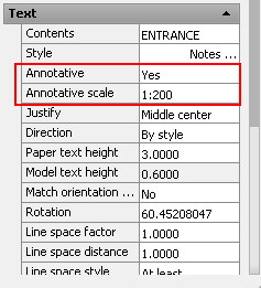
If you select the text and go to the properties Tab, there is a property called "Annotative". By default this is set to NO. Change it to YES to turn the Text into an Annotative one. There is a system variable, ANNOAUTOSCALE, that controls if new annotation Scales are added automatically or not, it has a lot of values, from -4 to 4, so see here what each value does.

In general, it is not recommended to have the ANNOAUTOSCALE set to automatically add annotation scales to all the objects, since that would increase the file size quite a lot. Alternatively, set the annotation Scale of the drawing by selecting it on the lower right side of the screen.


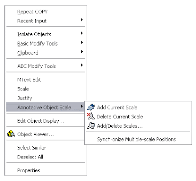
Then, you can simply select those objects you want to add new annotative scales too, right click --> Add Current Scale.


One more thing you can do is set different orientation for each annotative scale. This is very useful, because you might have an overall plan aligned to the World UCS (or North on top, or whatever) and then enlarged plans aligned according to the portion of the building/project you are focusing on. If you rotate the Text using the ROTATE command, it will rotate all its Annotative instances. If alternatively, you select the text, and on the properties tab you enter a new rotation, the new orientation will apply only to the current Annotative Scale. See the following image.


The 1:200 text is aligned in one direction, while the 1:100 text (the smaller one) is aligned according to the enlarged plan orientation. I am still trying to figure out how can I in AutoCAD Architecture, do the same for Space Tags. Will definetily post it whenever I find the way.

Annotative Scale applies to other AutoCAD objects such as Blocks, I will deal with that in a different post soon. Stay tuned

Show me more...