Showing posts with label Site Design. Show all posts

Importing Google Earth Topography to AutoCAD and then to Revit

Step by step on how to turn a Google Earth terrain into Revit Topography.
Català - Castellano - Deutsch
Was recently trying to import a Google Earth Terrain into a Revit Project to show an overall view of it. Since I did the research on how to do it, I will share it here.

I will basically list the 20 steps (15 for AutoCAD users) with a brief explanation if necessary, I think that's enough to follow the precess. You might not need to do some of the first steps, but the guide is intended for everyone who doesn't even know about Autodesk Labs. So here it comes:
  1. Be sure you have A compatible version of AutoCAD (2007 or newer in 32bit 2011 or 2012 in 64bit). Be sure you have A compatible version of Google Earth (5.x or 6.x) if you don't download it here
  2. Register on Autodesk Labs
  3. Sign In to your Account at Autodesk Labs
  4. Download the Google Earth Extension for AutoCAD based Products here
  5. Save PublishDWGtoGE.zip to your computer.
  6. Unzip the PublishDWGtoGE.zip file.
  7. Browse the PublishDWGtoGE folder that comes from the .ZIP file and find your AutoCAD version installer (first the year and then the 32 or 64 bit option)
  8. Run the installer (extension .msi)
  9. Open AutoCAD and Google Earth and check that in AutoCAD any of this commands works:IMPORTGEIMAGE, IMPORTGEMESH, GETIME, PUBLISHKML
  10. If they work, follow to step 15, if they don't do the follwoing steps
  11. Check the AutoCAD folder to see if the file named AeccDWGToGE.arx is there (it should), if it doesn't repeat the installation in case something went wrong, otherwise keep reading
  12. Run the ARX command in AutoCAD and enter L for Load when it prompts for an option in the command line bar.
  13. Browse to your AutoCAD folder and load the AeccDWGToGE.arx file
  14. Center your Google Earth view to the terrain portion you want to import
  15. Now run IMPORTGEMESH in AutoCAD (you must have Google Earth running)and the terrain will be imported to AutoCAD from Google Earth. If you are an AutoCAD user you are done, if Revit user keep reading
  16. Save the AutoCAD file (you can close Google Earth and AutoCAD after this)
  17. Open Revit
  18. Go to Insert Tab on the Ribbon and select Link CAD (or Ipmort CAD doesn't seem to matter here) and browse to find the Topography file you saved from AutoCAD.
  19. Now and finally go to Massing and Site Tab on the Ribbon and select Topo Surface
  20. Click on "Create from Import" and click on the imported topography from AutoCAD
Might seem complicated but it is actually not.


Show me more...

Revit: Using Building Pads Properly - Part II

A second not eon using Revit Building Pads the right way
Català - Castellano - Deutsch
On the previous post I talked about one of the issues I recurrently found when using Building Pads, their incorrect visual representation if you don't create them in a certain way. On this post I'd like to share a few points on how to use them properly to be able to get Cut and Fill counts, to be able to estimate the amount of Cubic Meters of Excavation of a project. On the documentation about Buiding Pads, there is information on how to create them and so on, but I think a few points are missing that are key to be able to use them the right way.

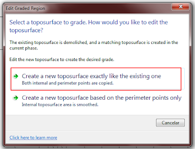
First of all, before creating any Building Pad, set the phase of the Topography to a Phase (I assume Existing would be the right one) and then set the phase of the view to the next one. Then, click on Graded Surface (on the massing & site Tab) select the topography, and on the dialog that appears, select the first option, see below, and simply accept the graded region like that pressing on the green "accept" symbol.


This will create an almost identical Topography to the existing one. If you don't do this first step, you will not get Cut and Fill counts when you create Building Pads. As I understand it, the count works as a comparison between one topography and the other, so without this step there is no topography to compare with.


At this point, you should have two identical surfaces, on on the Existing phase and one on the next one. I would hide the original topography at this point (Select it -> right click -> Hide in View -> Elements) so you know always that you are working with the new one that is the one you should modify.

All set until here. Now it is time to create the Building Pads. Very important point no to miss here. Revit allows you to create Building Pads by simply clicking on the Building Pad Button on the Massing & Site Tab. Don't do that. Be sure that first you select the Topography, then click on the Building Pad Button on the Massing & Site Tab. Otherwise, the Pad will be created, but sometimes (I haven't figured out why and how this happens) the Cut and Fill will not be reported on the Topography Schedule.


Create your Buidling Pad now, I am not going to describe this much because I think it is very simple and the documentation is good enough.

Next point, create a Topography Schedule if you don't have one (ideally your template should include one so you don't have to create one for each project). Then go to it and check what is being reported there. You will see probably three lines on the schedule, but you will not be able to know what is what. An important point to consider is Naming each Topography element differently. You should Name the existing Topo as "Existing" for instance, The copy as "Modified" or something like that and then each Topography created by adding the Building Pad with a different name that will allow you to identify it on the schedule. This is an example of a Schedule with the elements already named properly.


There is a Cut and Fill count on the "Modified" surface which I think comes from the slight difference between the two copies (the existing and modified topos) which might create a slight error on the total count, but my experience is that this amount is always negligible, compared to the total cut and fill counts obtained from the different topos related to the Building Pads.

Last two points to consider: First, creating a Buiding Pad, creates a Topography Element. It's important to understand that these are two separate but interrelated elements, if you delete one, the other will be deleted two (and the Modified topo will recover its previous shape).

Second, if you want to modify the Building Pad, you need to select the Building Pad Element (not the Topography Element) and then click on the "Edit Boundary" button that will appear on the ribbon. Unfortunately (as of Revit 2012) the Edit Boundary button does not appear if you are on a 3D view, so you will have to select the Pad from a Floor Plan view or similar. Since this might not be easy because all the elements that might show on that Floor plan view. I would select the Building Pad on any view where it is easy to select (I always have an Excavation 3D View with just Topos and Building Pads visible) deselect it, go to the Floor plan view and use the Select Previous function.

I think with this post and the previous one you can perfectly work with Topography and Building Pads and get accurate Cut and Fill quantities and the right visual representation. Hope this helps.

Show me more...

Revit: Using Building Pads Properly - Part I

There are a few things you need to consider when using Building Pads.
Català - Castellano - Deutsch
I've been using Revit Building Pads a lot recently to show the excavation needed for a project were are working on. The point was not only to show it visually, but also to use it to get the quantities for the excavation and so to be able to get an accurate budget for the works needed to build the underground levels of the building. This post deals with one of two different topics, the two topics are: one about some issues related with visual representation (on this post), the other about some issues related to the true BIM use of building pads, getting accurate quantity take-offs (on the next post).

Visual Issues: I realized that when using sloped building pads sometimes you get this sort of effect.


Getting this sort of "side wall" that shouldn't be there happens if you set the reference level of the Building Pad to be the top level and then slope it to go down to the level below.

If instead of that you place the Building Pad on the lower level and set it to go up to a higher elevation, then you will get the right effect, or to be accurate, a better visual effect. I think Building Pads can be still improved quite a lot.


Show me more...

SketchUp: Modelling a Terrain #01

What are the steps to follow to model a terrain in SketchUp? See them following this series of posts.
Català - Castellano - Deutsch
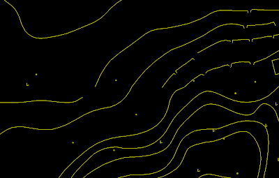
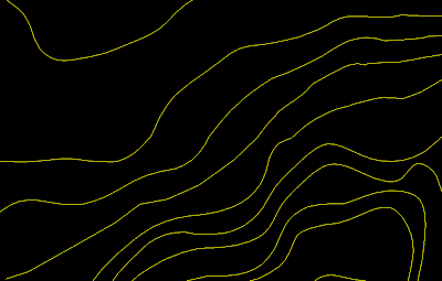
The first thing we need to do to be able to model a terrain, is to have clean topographic lines. This task is definitely better done on a CAD drafting platform such as AutoCAD.
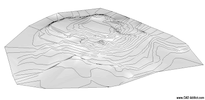
Ideally, we want to have topo-lines all connected, without gaps in them, and of course we want each of this topo lines to be at the right height. Getting this clean geometry is probably the most time consuming proces of modelling the terrain. See below for a "before and after" version of a typical topo file.


Once we have it, we just need to import the geometry to Sketchup and we are ready to start. To model the terrain, we need the SandBox tools. Although they come standard with sketchup, they need to be activated, so if you can´t see them, go to Windows --> Preferences --> Check that the box of the SandBox is Active --> Then go to View --> Toolbars --> Sandbox.

Before we proceed to use the sandbox tool to model the terrain, I strongly encourage you to use the Simplify Contours Plugin to simplify a bit the topo lines. Otherwise, the resulting terrain might be too heavy to handle.

Once we have done this, we simply need to select topo-lines, and click on the "from contours" tool in the Sandbox toolbar.


This will create the basic terrain. As you can see on the image below.


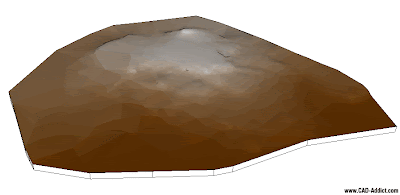
To represent it resembling a real life model I also added the sides and to be able to understand better how the terrain works, I used Chris Fullmer's "color by Z" plugin to paint the terrain. See below.


On future posts we will see how to add simple roads, how to place buildings, how to add vegetation, context terrain from Google earth, etc. I´ll try to use this same model for the other tutorials so anyone can follow them by downloading the file.
BTW, tomorrow is thanksgiving, so those who celebrate it, have a wonderful time with your families and/or friends. Don't get too crazy with the shopping deals...we are still on recession.

Show me more...

SketchUp Plugins: Simplify Contours

Simplify your inework to optimize your model. Specially useful for site modeling to make terrains simpler.
Català - Castellano - Deutsch
Site modeling can become an issue because the model can become very heavy, specially if we model complex topography. The best way to create a 3D model from your topographic lines is to use the SandBox tools. Simply follow this process.
  • If you have a cad file with the topo lines at the right height each, simply import it to SketchUp (File --> Import --> Select DWG as the file format)
  • Then select the topo lines in SketchUp and click on the "from Contours" button in the Sandbox Tool Bar.

This will create a terrain, but depending on how detailed your topo lines where, this might create a very heavy (in terms of memory) terrain. If you don't need 100% accuracy on how the terrain is modeled (and almost no one does) and want to optimize your model size, use the SimplifyContours.rb Plugin. This Plugin allows you to select the topo lines (Contours) and simplify them as much as you want/need. If your original topographic lines were splines in AutoCAD this is definitely a must, otherwise your model will become unbearably heavy.
This is a pretty old plugin, but still 4 years later it can save you from a struggle with a super heavy terrain model. Download it here if you please.


Show me more...

SketchUp: Site Design - Randomizing Vegetation

How do you randomize the scale and rotation of a series of objects? Wiht one of Chris Fullmer's Plugins!
Català - Castellano - Deutsch
On my recent post about site design, we saw how to easily place trees on site using the Drop plugin.
Once those trees where placed I found myself wanting them to be a bit more random. I didn't like the fact that all of them where the same size. The intention was to ebable to Select them all and turn them into randomly scaled-rotated copies. So I asked at the Sketchucation Forums, and I got the answer to my wishes.
Chris Fullmer's SCALE ROTATE MULTIPLE (clf_scale_rotate_multiple.rb) does exactly that. You simply select a set ob objects, and run the plugin through Plugins --> Chris Fullmer Tools --> Scale and Rotate Multiple --> Scale and Rotate All Randomly. On the dialog box you set the paramaters of maxim and minimum scale and maximum and minimum rotation and that's it. See how the All equal trees on the first image become randomly scaled on the second one.

IN this case the rotation doesn't matter because of the simplicity of the tree component, but if I ever replace it with a more complex/realistic tree, the instances will be also randomly rotated.
To download the Plugin and to see a quick explanation video, go to the Sketchucation original thread (need to be registered to download)


Show me more...