Showing posts with label Blocks. Show all posts

AutoCAD: Know the properties of a Nested Object

What is the layer of an Object in an Xref? Does it use color byLayer? List the properties of a Nested Object with this easy to use command.
Català - Castellano - Deutsch
If you need to know the layer of a nested object (to switch off that layer for instance) or other of its properties, you might want to use the XLIST command.
This command allows you to see the Object Type, the Block Name (in case the object is neted in a Block), the layer, the Color and the Linetype properties. The image below is an example of the results of using the XLIST command.


The command can also be called on the command line bar, using the -XLIST version. LazyDrafter reported recently that this helps when having very long XREF or Layer names, as the dialog box is sometimes too small to allow you to see the layer name complete.

Show me more...

AutoCAD: Use Curved Frames to Clip your References

Clip your Blocks or XREFs using curved polylines, circles, etc
Català - Castellano - Deutsch
A common problem found when using the XCLIP command is that it doesn't clip properly if the polyline we use has curved segments. The same way we can't use circles to clip Blocks or XREFs. If you try to clip a block using a polyline that contains curved segments you will see that along the curved segment the clipping is not done properly. See the following image. The block was clipped using the yellow polyline. The result is not satisfactory at all.


The first image shows the original block, the second one is the block clipped with the XCLIP command. As you see we need a work around this result. The work around is to use an Express Tool Command.

CLIPIT is an express tool command that will allow us to do what we wanted to do. CLIPIT will ask us to select the new clipping frame, that can actually be a POLYLINE, CIRCLE, ARC, ELLIPSE, or TEXT object. It works the opposite as the XCLIP command. With CLIPIT you first select the frame and then the Block, Image, Wipeout or XREF you want to clip. See the following image with the result.


What CLIPIT does, is turn the curved clipping frame into a set of segments. If you switch on the XCLIPFRAME and select the block, you will see that the frame is actually made of straight lines. See it below.


The only bad part of this express tool, is that so far (till version 2009) it doesn't allow inverted clips. We talked about how useful inverted XCLIPS can be on a previous post. Hopefully in future versions of AutoCAD this will be solved.

Show me more...

AutoCAD Weekly Block #08: Cobblestone Pattern

Download this block and learn about the SUPERHATCH command
Català - Castellano - Deutsch
This week's Block is the first that is not a dynamic one. The reason for that is that I remembered I had not talked in here about the SUPERHATCH command. As you will see, the SUPERHATCH command allows you to hatch an area with any custom made hatch.
Why is it in the weekly block section? Well the way SUPERHATCH works involves Blocks much more than it involves hatches (it actually does not involve hatch patterns at all.
The block for download is a cobblestone pattern that my company uses in some of the projects (not everyone gets to work on Zaha's futuristic shapes...lol). You can Download it here. See the snapshot of the block below.


We use this block to hatch certain areas, and the way to do it quick and efficiently is using the SUPERHATCH Express Tool. When you call the SUPERHATCH command, you will see the following menu.


Here you will select Block as an option and use the downloaded "CAD-Addict.com cobblestone" Block. After doing this, simply follow the prompts, basically, you simply need to pick the initial position, rotation and scale, and then pick an internal point of the area you want to Superhatch.
The result will be a set of blocks clipped to fit the boundary selected. See below.


Remember that when selecting "internal point" if the drawing is heavy the computer might crash, so I would recommend you to switch off any unnecessary layers before attempting this operation.

This command has more options that have not been explored in this post, but I think you can get an idea of how powerful this is.

Show me more...

AutoCAD Weekly Block #07: Dynamic Escalator - Side Elevation

Download this block and learn about setting angles for Stretch Actions
Català - Castellano - Deutsch
I am a bit behind on my weekly blocks but the truth is that the past weeks are being kind of crazy. Anyways, to catch up with this here comes issue #07 of the AutoCAD Weekly Blocks. This week I am sharing with you a dynamic block for an escalator that I created at work. The idea behind the block is that with a single escalator block we could cover any floor to floor height. First let's see a pic of the block so you know if you have interest reading further.


The original linework is a simplified version of a block obtained directly from Schindler, so the dimensions should be accurate for that manufacturer and very close for any other.

To turn the block into a dynamic one that stretches to fit to any floor to floor height we only need one Linear Parameter and a Stretch Action. Although the stretching we want to do has to be along the 30 degree angle defined by the escalator, we don't want to set the linear parameter in that direction. Let me explain you why. If we do so, the distance of the linear parameter will be the longitudinal distance of the escalator, that way, we would need some guides to know till what point we want to stretch it. What I want is to define the linear parameter to define the floor to floor distance but have the escalator stretch along the 30 degree slope. As complicated as it sounds in writing, it is very simple when it comes to defining the parameter and action. See the image below.


I defined a linear parameter to describe the floor to floor height (Distance in the image) and a Stretch Action. You can see the Stretch Polygon associated to the Action in a dotted line when you select the action. If we simply defined the parameter and action this way, the block would stretch vertically following the direction of the Linear parameter (distance). Instead we want it to stretch along the escalator direction (the 30 degree slope). The simple extra step we need to do for this is to select the Stretch action, go to properties and set the right angle.


In this case, the right angle is 300 (instead of 30) since the Angle count starts with the Distance parameter, not with the XY axis.
As you can see it is a very simple procedure and now you can use a single block while your boss decides what floor to floor height he really wants. You can select the grip of the block to extend it or, easier, go to properties and set the distance to the floor to floor height you need. You can Download the Block Here.

Show me more...

AutoCAD: Placing Objects Along a Curved Path

Need to place obects evenly along a curved path? Two Commands will do that for you.
Català - Castellano - Deutsch
Placing objects evenly spaced and properly aligned along a curved path is something I have to do pretty often. Either if it is because I need to place trees along a curved sidewalk or because I want to have a floor pattern that smoothly adapts to a curved shape. The commands DIVIDE, and specially MEASURE are ideal for this task.

These two commands work in a very similar way, DIVIDE let us place objects evenly along a path, dividing the path in the number of segments that we assign, while MEASURE will allow us to choose the distance between elements. To use these commands to place objects, we need to make a block of the objects we want to place along the path. Name the block with an short and easy to remember name because you will have to type it manually.

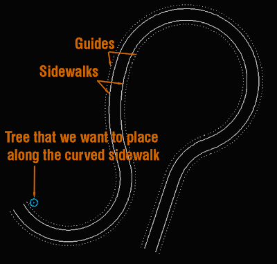
If for instance, we want to place trees every 10 meters along a sidewalk of a road, we need the block of the tree we want to place (for this example let's imagine a block called tree01), we need the entire curved sidewalk to be a polyline, and to make it easier we need a guide paralel to that sidewalk curb that will be along which we will place the trees. See the image below that describes the needed elements.


Once we have this, we simply need to run the command MEASURE (you can simply type ME), select one of the guides when prompted "select object to measure". Then we will enter "B" and ENTER to be able to select the block. On "enter the name of a block to insert" we type "tree01" or whatever name of the block you want to place. On "align block to object" we will generally say YES. The last thing to do is to "specify length of segment" which is the distance we want the Blocks to be apart from each other. If we repeat the process for both sidewalks, the result will be something like this.


We will use MEASURE most of the times to do this sort of block placements because it allows us to pick the distance between blocks. If we knew the number of blocks we would like to place instead of the distance between them then we would use the same procedure with the DIVIDE command instead of MEASURE.


Show me more...

AutoCAD: How to Modify the XCLIP Frame Without Redrawing it

You can easily edit which part of an XREF is clipped without redrawing a new polyline.
Català - Castellano - Deutsch
A few months back a wrote a post about the XCLIPFRAME system variable. What I didn't know back then is that the frame shown with this system variable could actually be edited.

For those who don´t know what an XCLIP is: with the XCLIP command, we can clip (hide) part of a Block or XREF. This will allow us to keep the Block or the XREF unexploded while showing only the part of it that we want in our drawing. As I already mentioned before, I hate people who explode blocks as a hobby, but I understand they do so because they don´t know they have these options.

So back to editing the XCLIP Frame, if we set the XCLIPFRAME system variable to 1, we will be able to see the frame that is used to hide part of the Block or XREF. This frame can be modified by selecting it and moving its grips. In many cases, when we have created a very complex XCLIP Frame, this becomes extremely useful so we don't have to redraw the polyline we used to clip de Block or XREF while still allowing us to hide or show a different part of the object. I made a quick video showing the power of the XCLIPFRAME system variable. Check it out below.


Show me more...

AutoCAD: How to Make a Block Unique

How do you turn one instance of a block into a unique block in a single an easy step? There is an easy way.
Català - Castellano - Deutsch
If you are a SketchUp and AutoCAD user like me, probably you miss the "make unique" option from SketchUp when you are using AutoCAD. For those who do not use SU, Make Unique will turn an instance of a Component (Blocks in SketchUp are called Components) into a Unique one, allowing us to modify it without affecting the other instances of that Component.
I always miss this is a feature in AutoCAD, but lately I came to realize that there is a way to do the same (only for 2D blocks though). The trick is to use the FLATTEN command. If we select "Sample Block 01" and run the FLATTEN command, the result will be a flattened version of the same block called "Sample Block 01-flat1". Because the new block has a different name we can modify it without affecting the other instances of that block. So the result achieved would be the same we get in SketchUp using "Make Unique".
This, of course, only works in 2D, since the command FLATTEN flattens linework, it would turn a 3D block into a 2D one.

Show me more...

AutoCAD: Scale Objects in one dimension only.

There is a way to scale objects only on one axis.
Català - Castellano - Deutsch
I used to work with Microstation long time ago and that program has the scale in one dimension as a standard option of the scale command. Unfortunately AutoCAD doesn´t. If you need to scale objects on one dimension there is a way in AutoCAD to do it though.
You need to select the objects you want to scale and create a block out of them. Be sure to create the block with the "scale uniformly" option unchecked. Then, this block can be scaled in one direction by modifying the X or Y scale. Once you have the geometry scaled as you wanted you can explode the block.
Of course it is not as precise as using the scale command, but so far it seems to be the only way to do this.

Show me more...

AutoCAD Weekly Block #06: Dynamic Graphic Scale

Download this Block and learn a bit about Visibility states in Dynamic Blocks
Català - Castellano - Deutsch
This week's Block is a Graphic Scale created as a dynamic block that will be fit for the following scales: 1:50, 1:100, 1:200, 1:500 and 1:1000. The block is meant to be used on paper space. Download the block or see the image below.


The Block is created using a visibility state for each scale, so only the text that fits that scale will show. On the previous image you can see how if you click on the triangular grip of the bock, the different visibility states are shown.
The process of creation is simple. Once you have the linework and text for one of the scales, create the different visibility states for each of the scales. Copy the text and change it values to the one that fits the next scale and hide hat text on the scale you don't want it to be shown. Repeat the process for each scale you want to create. For more details on how to create and modify visibility states check this older post. To summarize what it is important check the buttons related to visibility states in the Block Editor and what they are for. They are situated on the upper right corner of the block editor interface. They are the following.

  1. Toggles objects on other visibility states on and off.
  2. Makes an object visible in the current visibility state
  3. Hides an object form the current visibility state
  4. Calls the visibility states dialog box (where we will create different visibility states)


Show me more...

AutoCAD Weekly Block #05: Dynamic Door

Download this Block and learn about Flip Parameters.
Català - Castellano - Deutsch
On this week's Block we will quickly see how to use the Flip Parameters/Actions. To do that we will use a block of a 80cm door, which in metric unit system would be the most common door you would need to use.
What we want to achieve adding the flip parameters is to be able to flip the door to open to one side or the other without the need to actually using the MIRROR command. So basically we need to add two flip parameters, one to flip the door to open right or left and another one to flip the door to open in or out. Download the block and you will see what it can do.

As you can see in the image above, when the block is selected it shows two arrows. This two arrows allow us to flip the block. But lets quickly see how this arrows work. If we enter the Block Editor, this is what we see.

What I have done is to create two Flip parameters (Flip State and Flip state 1 on the image) following the two perpendicular axis of the block. Then, I added a flip action to each of those parameters, and selected the door and the arch as objects. Nothing else, simple but effective. Of course if you are a user of AutoCAD Architecture this block is useless, but for those using plain AutoCAD this might be useful.

Show me more...

AutoCAD Weekly Block #04: Dynamic Vanity/Washbasin

Download this Blog and learn to use the Move action and distance multipliers to keep an object always centered
Català - Castellano - Deutsch
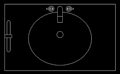
This week's Block is a Vanity with stretchable properties and that keeps the washbasin always centered. You can download the block clicking on the image below.

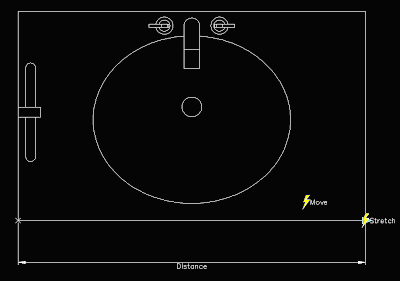
The block is pretty simple, it ahs only one parameter, the distance from one edge to the other, and two actions. The first action is a Stretch action to stretch the contours of the vanity. The second action is a move action to move the washbasin. I have linked both actions to the same parameter for simplicity and to show you how to keep an object centered when modifying a dynamic block. See the Block editor snapshot of the block.

We want the washbasin to stay centered when we stretch the block. This, if you think about it, means that for every unit we stretch the block, we want the washbasin to move 0.5 units.
To do this we need to set a distance multiplier for the move action. We can do that two ways. First one, when you create the action, at some point in the command line you will see this.


If you press M, you will be able to set the 0.5 as distance multiplier. The other option you have, in case you forgot to set this when you created the action, is to select the move action, and go to the properties tab. There, under overrides, you can set the distance multiplier.


What is the other option you see near multiplier? Offset. I will talk about it on next week's Weekly Block.

Show me more...

AutoCAD: Weekly Block #03 - Multipurpose Sports Court

Download this Block and learn about Visibility States for Dynamic Blocks
Català - Castellano - Deutsch
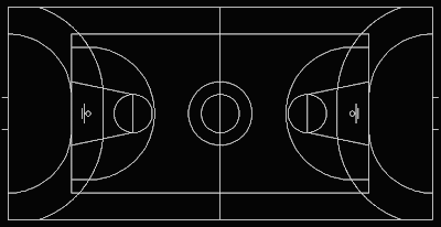
This week's block intends to show you how to play with the visibility parameters of dynamic blocks. The idea behind the Block is to be useful when showing multisport venues (I have to say that this block is mainly useful for European Countries where combining a Basketball court 28x15m with a Handball Court 40x20m is the common practice. See too, that the Basketball court block is based on the FIBA regulations, not NBA or NCAA).
To give you a better idea see a snapshot of the block. You can download the block here or clicking on the image.

The block consists of 2 other Blocks Embedded in it. One for the Basketball Court, and one for the Handball Court. But because I wanted to use a single block to show the different possibilities (i.e. Basketball court Alone, Handball Court Alone or Both together like in the snapshot) I added visibility states to achieve it.
To do that once the block is created, you need to open the Block Editor and add a parameter. When asked which parameter you want to add, type "V" for visibility. Once the parameter is set, you need to create the visibility states. This can be easily done with the controls on the upper right corner of the Block Editor interface. See the image.They are the following.


  1. Toggles objects on other visibility states on and off.
  2. Makes an object visible in the current visibility state
  3. Hides an object form the current visibility state
  4. Calls the visibility states dialog box (where we will create different visibility states)
So the steps we will follow are:
  • first we have to do is click button #4 and create a new visibility state called Basketball, antoher One Called Handball and rename the existing one as Both.
  • Having Basketball visibility state active, select the Handball court and click button #3 to hide it. (the court will diappear if you didn't click button #1, if you did the court will fade)
  • Turn Handball visibility state active, select the Basketball Courtand hide it (button #3)

Pretty simple isn't it? Now exit the block editor (saving the changes) and see how when you select the block there is a new grip that when you click on it will show the 3 visibility states. Pick the one you want and you will see if you did the process right.
If you want to repeat the process I showed here you can download this block that doesn't have the Parameters and Visibility states Added.

Show me more...

AutoCAD Weekly Block #02: Dynamic Dinning Table

Download this Block and learn about Standard Sizes for Dynamic Blocks
Català - Castellano - Deutsch
Last week I started the Weekly Block section with a Dynamic Wardrobe block and a tutorial on how to use the Stretch and Array Actions.
This week´s block is a Dinning Table block. You can download it here. The block is dynamic too, so it can be transformed from a dinning table for 4 people to a table for 6, 8, 10 or 12 people.
To do that, I used a Linear parameter and Stretch and Array actions. Since I already explained on last week's post and on a previous one how to use these features, I am going to skip this explanation today.
What we will focus today is on how to set standard sizes for dynamic blocks. Once we have the Block set with the parameters and actions associated working properly we want to limit how the block can be modified.
In our example, we want the length of the table to change in increments of 0.80 meters. What we have to do is the following. Being in Block Editor mode, select the distance parameter you want to set standard sizes to. On the properties palette go to Value Set --> Distance Type and select List.

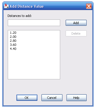
After that we need to add the values the list. Click on the 3 dots on the right of the "Dist Value List" Box. A dialog opens like the one below where you can add the list of values you want the distance parameter to take.

The 1.20 value is there because it is the value of the distance parameter when we created it. We will add the values 2.00, 2.80, 3.60 and 4.40. Now, you can exit the block editor and test the block. You will see that when you select the grip to stretch the table, some markers appear on the screen showing you the possible sizes coming from this list that we created.
Since we set the Array column offset distance to be also 0.80m any time we change the length of the table we will see some extra chairs appearing.
The great thing of dynamic blocks is that if used smartly they can simplify things a lot. Before you probably had a Block for a table sitting 4 people, another for a table sitting 6, another for a table sitting 8 etc. Now, you only need one configured like this one and it will work for all them.
Download the Block Here

Show me more...

AutoCAD Weekly Block #01: Dynamic Wardrobe

A Wardrobe Block 60cm deep that can adopt any length.
Català - Castellano - Deutsch
I am going to start sharing weekly some of the Blocks I've been creating for some of our projects. Some of them, like this one, will help us go through some of the basics on how to deal with Blocks. In this case, we will quickly go over how to create a Dynamic block again (there is a longer post from some months ago explaining in more detail How to Create a Dynamic Block).

Download the Block or see the image of the below.


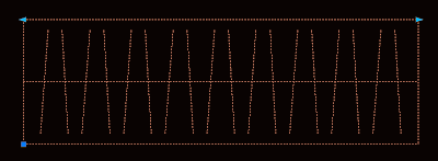
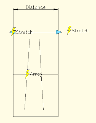
As you can see in the image, the block shows two arrows on its upper corners. These are the Grips that allow us to modify it's length. If you enter the Block Editor (select the Block and type BE) you will see something like this.

Lets see what each of the elements found does. Distance is teh Linear Parameter, it defines a distance that can be modified. Stretch is an Action. Actions associated to parameters is what creates the interactivity on dynamic blocks. The stretch and stretch1 action stretch the wardrobe on its length. The other element is Array. Array is another Action, and what it does is to repeat the two tilted lines when the block is stretch.
The process to create this block is simple. Once we have the basic linework that you see inside the Blockeditor (the outline and the two tilted lines) we do the folowwing:
  • We create a Block out of this line work with origin on one corner.
  • Enter the Block Editor, BE (do not edit block in place with REFEDIT command)
  • We add a Linear Parameter from one corner to the other.
  • To add the array action, click the actions button, select the distance parameter and enter array as action type. Then select the 2 tilted lines as objects and enter the distance you want the copies to appear my block uses 0.2m, but you can set it to anything you want)
  • Now we add the Stretch Action. Again click the Actions button, select the Distance Parameter, Select Stretch as type of action, select one of the Distance parameter points, Draw a Polygon as you would do usng the STRETCH command and select the objects you want to Stretch. (be sure to avoid selecting the tilted lines)
  • Do the same for the other side of the wardrobe with a new Stretch Action.
That´s it. You have created a dynamic Block. Try how it behaves. Remember that I will be sharing more blocks regularly. You can subscribe to the blog feed to not miss any of them, or just come by often.

Show me more...
AutoCAD:Explode Unexplodable Blocks

Do you find yourself unable to explode certain Blocks? Don't despair, the solution is easier than you might think.
Català - Castellano - Deutsch
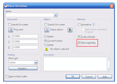
When a Block is created there are several options that sometimes are overlooked. One of this is the option to not allow the block to be exploded. If you don't know that this exists, you might find yourself unable to explode a block that you really, really, really need to explode (I am no fan of Block exploding, I mostly hate people who do that as a hobby, but sometimes you do need to explode them).
The trick is to open the block definition dialog box (type "b", or "block") without selecting anything. Then on the drop down list search for the block you are unable to explode. You will see that the "allow exploding" option is unselected. Select it and click OK. Now select the Block, enter X for EXPLODE. The Block should explode.
As I said before, be careful about exploding blocks (specially in a multiuser environment). If they have been created as blocks is for a reason, so exploding them might screw up someone else's effort. Remember that Blocks can be scaled, clipped using the XCLIP or CLIPIT commands, etc so consider other options before exploding them.

kick it on CadKicks.com

Show me more...
Rhino Plugins: Block Editor

Rhino does not have Block Editor by default, but there is a plugin for that.
Català - Castellano
If you start using Rhino like me coming from an AutoCAD, Microstation and/or SketchUp background you'll be used to create Blocks, Cells or Components, to edit them later.
Rhino by default does not have a Block Editor so you might find yourself a bit lost if you imported a file in Rhino from other applications that work with Blocks or similar entities.
No problem. Rhino, very similarly as SketchUp, has a wide range of Plugins to enhance its functionality. One of this is the Block Editor plugin, that will add the needed functionality to your Rhino. To download it go to this link. The Mcneel website has plenty of information about how to install plugins.
You need to use the PlugInManager command to load the Plugin, browse to the location where you have the plugin stored and click OK. After that you can select a block and run the command InPlaceBlockEdit to edit the block.
To manage Blocks Rhino has the BlockManager that allows you update and delete existing blocks and linked files.

Show me more...

AutoCAD: Fields in Dynamic Blocks to Display Properties

If you need to display certain changing properties of a dynamic block you can do it using Attributes and Fields
Català - Castellano
In a previous post, I went through the process of creating a dynamic block of an escalator with dynamic properties. The block allowed its length and width to be modified using parameters and actions. We will use that block as a reference to explain how to add a dynamic attribute.
We will attempt, as an example, to add a text that will show us the width of the steps in the escalator block. To make things simpler, you can download the block here. We will follow these steps:
  • Enter the Block Editor mode (type BE)
  • Define an attribute (ATTDEF)
  • Insert a field on that attribute
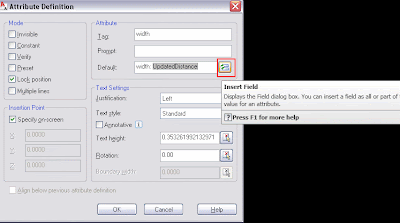
Once we are in Block Editor Mode and we type ATTDEF we will get the Attribute Definition dialog Box. Here we can tag the Attribute as Width. For its default value we will ad "Width: " and after that is where we will insert the field. To insert the field we will click on the Box near the Default value Box. See the picture below.

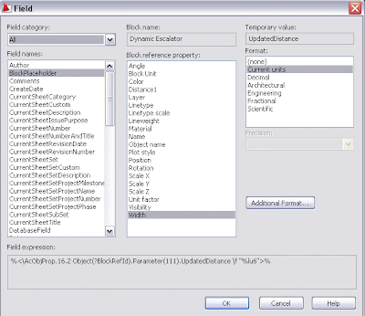
The type of field we need to add is a "Block Place Holder". We will see all the parameters of a dynamic block listed here, plus other properties such as layer, color, etc. In this case I renamed the parameter "Distance" as "Width". So I select this one.

One extra step that helps in the process is to select the attribute to be constant (so we don't get a prompt asking its value).
Update: Make sure that the attribute is NOT set to constant, otherwise it will not update when beeing modified.
Wen we finish defining the attribute we simply exit the Block editor mode and insert a new instance of the block. The new defined attribute will appear, and if we change the width of the steps (and REGEN the drawing) the field will update with the new distance.

You can download the same block with the dynamic attribute here to see it for yourself.kick it on CadKicks.com

Show me more...