Showing posts with label Blocks. Show all posts

AutoCAD: Full power of the LAYFRZ command

Trouble freezing layers on XREFs or Blocks? The solution is on the command line
Català - Castellano
Many commands in AutoCAD have more options than we really know. We just need to take a look at the command line once the command is active to find these extra options. LAYFRZ is not an exception to this rule.
We often have trouble trying to freeze layers within XREFs or Blocks. THis is because of the hierarchy system of AutoCAD, but also because the LAYFRZ command might be configured wrong.
Once we start the command, we have the chance to type "S" for settings and we will access a world of possibilities. What is basically important to understand is the set of options regarding Block Nesting.


We have b (for Block) that will do 2 different things:
  • If a selected object is nested in a block, freezes the layer of that block.
  • If a selected object is nested in an xref, freezes the layer of the object.
E (for Entity) will freeze the layers of the selected objects even if they are nested.
N (for None) would freeze the layer containing the block or Xref.
I think it is good to remember that with any tool there might be some extra options that we are not considering that we can discover by paying some attention to the command line.

Show me more...

AutoCAD: Creating a Tool Palette with multiple Blocks at Once

You don't need to manually add each Block to a tool palette, it can be done with just a few clicks.
Català - Castellano
Not so long ago, I wrote a post explaining how to transfer Tool Palettes from one computer to another. The following post also explained how to create a new group of palettes.
What I found out today is how to create a new Palette from a file. This is very useful if we want to generate a palette with a lot of Blocks that we have stored in a single file. With just a few blocks, or with blocks in different files, we would manually drag and drop the blocks into the new palette. That becomes tedious if we have to do it for a lot of blocks. The solution is quite simple:
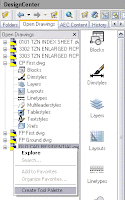
We make sure first that we have active the group of palettes where we want to add the new one. We also need to have the drawing containing the Blocks open. From the design center ("Ctrl + 2" or ADCENTER command) we select the file with the blocks we want to add, right click it and select "create palette". See the image for a visual aid to do this.
The result will be a palette with the anme of the file, and ALL the Blocks that the file contained, organized alphabetically.
Thanks to Aarti for this tip.
kick it on CadKicks.com

Show me more...

AutoCAD tutorial: Creating a dynamic block 1.0

Learn step by step how to create a dynamic block.
Català - Castellano
Dynamic blocks are a very important resource to increase productivity. What would require several different blocks can be achieved with a single dynamic one if we know how to give the right editing properties to them.
In this first tutorial we will create a dynamic block for an escalator. The block will be able to be stretched to have different step widths, overall lengths (to cover different floor to floor heights) and some other cool properties.
First of all we have to create a standard block. I got the escalator DWG from Schindler, the block is good enough for the precise height you request it. This is the drawing we will start with.
We will name this block Dynamic Escalator. To make this block a dynamic block we have to add Parameters and Actions to the block. To do so, select the blog and type BE (Block Editor). Inside the Block Editor you will find a series of buttons that will allow you to do that.

We have to plan what we want to do, and probably you will have to do things twice or trice till you make the block work as you want. To start we will set the parameters and actions that will let us modify the step width of the escalator. This are the steps we will follow.
  • Click the parameter button
  • Select Linear as Parameter Type.
  • Select the two edges of one of the steps.
  • Choose to show only one grip.
This is how the parameter should look after we created it.

Now, we need to add an action to this parameter. This are the steps to follow.
  • Click the Action Button
  • Select the Parameter
  • Choose Stretch As the Action Type
  • Select the Grip
  • Select the stretch Polygon (like you would select the objects using the STRETCH command)
  • Select the objects to be stretched.
The block should resemble to this:
Try to save and go out of the block editor. Check that the block behaves the way it is expected. If it does we will continue adding parameters and actions.
Next we will make the block stretchable in length. This will require more than one action since we not only want to stretch the lines, but also make extra steps appear when we stretch the block.
We will do the following:
  • Add a linear parameter to the length of the block
  • Add a stretch action to stretch all the lateral lines of the escalator.
  • Add an Array action to make new steps when the block is edited.
The first think we will have to do is to erase all the step lines except one so we can use the array action properly. With that done, we add a linear parameter to the length of the block. See that I also added some markers on a non plot layer so I know certain points where the length of the escalator corresponds to certain floor to floor height (like 5m, 6m, 7m etc.). The block should look something like this at this point (inside the Block Editor Interface):


We want the step lines to show all the way from end to end of the escalator. We need to add an array action to the same linear parameter that we are using for stretching the block in length. We follow these process:
  • Click the action Button
  • Select the linear parameter.
  • Choose Array as the action
  • Select the single step line we have when prompted to select objects
It is important that the linear parameter starts on the step line and ends where the steps are supposed to disappear, otherwise you might get step lines out of the boundaries they are supposed to be. Again, save the block and go out of the block editor interface. Check that the parameters and actions added work as desired.
We still want to add a couple more parameters to the block. First we want text and an arrow that shows if the escalator is going down or arriving from the level below. We will use the text DN for going down, and AR for an escalator that arrives to the level we are showing. First we prepare the block for the actions we want to add.
  • We type both texts AR and DN on the same exact position.
  • We mirror the arrow head so we have a line with arrows on both sides.
It should look like the image above. What we want to do is to be able to use the same block either for an elevator going down (DN text with the arrow pointing away form the text) and an elevator arriving to the level we are showing (AR text with the arrow pointing to it). We will have to use a different parameter type called Visibility. It is important to know the buttons related to the visibility parameter. They are situated on the upper right corner of the block editor interface. They are the following.

  1. Toggles objects on other visibility states on and off.
  2. Makes an object visible in the current visibility state
  3. Hides an object form the current visibility state
  4. Calls the visibility states dialog box (where we will create different visibility states)
So the steps we will follow are:
  • first we have to do is click button #4 and create a new visibility state called AR, and rename the existing one as DN.
  • Having DN as active visibility state select the AR text and the arrowhead pointing to it and click button #3 to hide them. (the objects will diappear if you didn't click button #1, if you did the objects will be faded)
  • Turn AR visibility state active, select DN text and arrowhead pointing away from it and hide them (button #3)
Let's check if it worked. Save the block and get out of the BE interface. Select the block and click on the grip corresponding to the visibility parameter. You'll be able to select the visibility mode you want so with the same block you will be able to show both an escalator going down and another arriving to the level we are. See the too pictures below.

The last edit I added to the block is a rotation aprameter and action that allows me to rotate the text to any position I want. The idea is that no matter in which angle the escalator is placed, the text should always be facing the right way. See the image below to understand what I mean..
I am not going to detail the steps for this since it is pretty simple and similar to the rest of the process. Just think of using a rotation parameter and action applied to the center of the text.
If you want to check the escalator file, you can download it here.

Show me more...

AutoCAD Express Tools: NCOPY

Copy entities from nested objects or files.
Català - Castellano
The NCOPY command is a very useful one when we are working with XREFs or Blocks. NCOPY stands for Nested Copy which means that it will allow us to copy objects that are nested in XREFs and Blocks.
Instead of opening the xref and copying an pasting the entities we want to move from the reference file to the drawing we are at we can use NCOPY and directly copy this entities without opening the file.
The same applies for Blocks, no need to open the Block Editor to copy objects from inside the block to outside of it.

Show me more...

AutoCAD Modifying the Background Color in the Block Editor

Get rid of the nnoying background color of the Block Editor.A question a lot might have is "who did choose that annoying color for the background color in the Block Editor?" I think it is realy a bad choice and makes it hard to work in it because the creamy color will be similar to a lot of lines and will make it hard to work.

It is easy to change the Background color. We just have to go to

Format --> Options --> Display Tab


We click the "Colors" Button. This will bring us to the "Drawing WIndow Colors" Menu. Where we can actually change the display colors of almost anything in AutoCAD. TO change the Background Color of the Block Editor we select "Block Editor" On the Left and "Uniform Background" on the second option. Then on the right pper corner we can change the color to the one we want. A lo of people like to use the same black color as in normal drawing, I personnally prefer to choose a dark grey, so although easy to work with it still reminds me that I am in the Block Editor and not in the main drawing. See the image beow for details.


Quick Reference
Format --> Options --> Display Tab --> Colors --> Block Editor --> Uniform Background --> Choose Color

Show me more...

AutoCAD 2008. Inverted Xclips

Clip the inside of the frame inside of the outside when using the XCLIP command.
Català - Castellano - Deutsch
From 2008 version we can create a cutout in the middle of an xref or block using xclip. Before selecting or creating the polyline we have an option called "inverted clip" which will make the part of the object inside of the polyline disappear instead of the outside.
If you look at the command line, after running the XCLIP command and have selected teh object you want to clip, you will bsee this line:
[Select polyline/Polygonal/Rectangular/Invert clip] :
If you type "i" and press enter, you will be inverting the way the XCLIP command works, so instead of keeping the inside of the frame and hiding the outside it will do the opposite. Once you have clipped the XREF you can actually modify its frame later, see this post and video for how to do that.

Show me more...