Showing posts with label System Variables. Show all posts

AutoCAD: Select objects before running the Command

This is a common problem after having FATAL ERROR crashed. The settings go wrong and you can't select the object first. No worries, it has an easy solution
Català - Castellano - Deutsch
Norman asked me recently the following question:
My CAD had a fatal error.
Where I used to click on a command then an object (eg: select block then copy)
I now have to click on the button then select object (eg: click on copy then select the block)
Can anyone help me change this back?

This is a common problem that occurs after crashed. For some reason there is a system variable that goes nuts after the fatal errors.

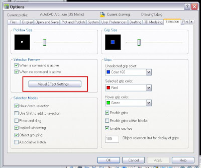
This system variable is called PICKFIRST. It controls what is called the "noun-verb" behavior of AutoCAD. This is the logic behind the variable.

0 - Turns OFF PICKFIRST. Select objects after a command is invoked.
1 - Turns ON PICKFIRST. Select objects before or after a command is invoked.

I can't tell you why this happens, but at least now you know how to solve it.


Show me more...

AutoCAD: PEDIT Command Without Confirmation

A trick to speed up the PEDIT command
Català - Castellano - Deutsch
PEDIT is a command that allows us to edit Polylines. It also allows us to edit lines, arcs and splines, by asking us the question we many hate
"Object selected is not a polyline
Do you want to turn it into one? "
Although this might be useful to remember that the geometry selected is not a polyline, it turns to be an extra click that we would love to skip. We will skip it from now on thanks to Josh from Lazydrafter.
Josh posted recently about the PEDITACCEPT system variable. The variable is by default set to "0", and that is why AutoCAD asks us that annoying question. Well, set it up to "1", and the question is gone. Now it takes no extra step to edit lines, arcs. Spline still ask for the conversion factor, but still you'll be saving couple of clicks. All to work faster!


Show me more...

AutoCAD 2010: New System Variable to Fade XREFs

AutoCAD 2010 has a new system variable to fade XREFs.
Català - Castellano - Deutsch
New versions come sometimes with some nice surprises. One I just discovered by using AutoCAD 2010 at work is the XDWGFADECTL system variable. We had seen long ago on a previous post how to control the fading of locked layers and the objects seen outside the REFEDIT mode. Just as a quick reminder on that since that is a very old post.

LAYLOCKFADECTL directly controls the intensity of the fading of locked layers.
XFADECTL is used to control the fading when we enter the REFEDIT mode (everything that does not belong to the XREF that we enter to edit in place will be faded).

This was what we had available so far. In case we wanted to fade the XREF, my common procedure was to set the fading of the LAYLOCKFADECTL to between 30 and 50% (depending on the screen), be sure that all my XREFs where in one layer, and lock that layer. This would allow me to see my XREFs fades, making very easy to understand what was in the current drawing and what was a reference.
The only problem with this is that sometimes, when we had to move those XREFs, we had to unlock the layer and lock it after finishing the operation. Minor nuisance maybe, but it has disappeared from now on.

XDWGFADECTL is one of the new system variable added to AutoCAD 2010 that allows to control how XREFs are faded. It is useful. It might seem a minor tweek, but when you are using a dwg as an underlay to draw something else, it is really practical to see this dwg faded. And although this could be done before with the locked layers fading, now we have a second way to do it to suit every situation (or almost every)

Remember that there is a list of all the system variables that have been explained at CAD-Addict following this link.

Show me more...

AutoCAD: SaveAs 2004 Script

A script to save your drawings on a previous AutoCAD version.
Català - Castellano - Deutsch
As I promised on a previous post about Running Scripts on Multiple AutoCAD files, here comes the script to save your files as 2004 version. I found the need of this script recently, when a collaborator of mine was working with AutoCAD 2004 (i didn't know that in advance) and I was working with 2010. After finishing the tweaks on some of the files, he asked me "can you convert them to 2004, otherwise I can't read them". Well there were nearly 40 drawings, so I had no intention to save them one by one to 2004 format. I set myself to generate a script to do that for me.
This is the script file SaveAs2004.scr and let me easily explain how it works. Let's analyse it line by line.
FILEDIA 0 - This line turns off the dialog boxes (see this post for more info)
SAVEAS 2004 Y - this part is the proper saving as 2004 version. we call the saveas command, stipulate 2004 (or any other version we want) and then click yes, because the program will ask us if we want to overwrite the existing file. note here that there are 2 spaces between 2004 and Y, this is due to the fact that the first is to enter 2004, and the second is needed, to confirm the file name. (If you want to understand this better, run the different commands manually with the FILEDIA system variable set to 0, and you will be able to see all the steps I am following).
FILEDIA 1 - here I simply wanna make sure that after running the script the settings return to what they were, so i set the FILEDIA SV back to 1.
CLOSE - Closes the file, be sure that there is a space or an enter after close, since it is easy to forget that being the last text in the script file. This is generally not neecessary if you use a batch scripting program such as Autoscript or ScriptPrp, but in case you run the script directly in one file, this will close the file after running it.
That's it, now you have a script to save as 2004 version. Replace 2004 by, R14, 2004, 2007, 2010, Standards, DXF or Template, and you will save in that format.


Show me more...

AutoCAD: Get Back the Menus and Toolbars - aka Ditch the Ribbon

Do you hate the ribbon? Do you want to get back your old menubar structure with toolbars? Easy and simple
Català - Castellano - Deutsch
I hate the ribbon, I confess it. It is not only the Ribbon in AutoCAD, its the whole Ribbon concept, I hate it too since it appeared in the new version of the Office package (2007).
Fortunately, AutoCAD allows you to switch back to the old system, it is a pretty simple process. You just need to do the following:
  • Type RIBBONCLOSE (it will close the ribbon)
  • Enter MENUBAR in the command line and type "1" as a new value (it will show the menubar)
  • Then go to the EXTRAS Menu and go to Toolbars, here you will be able to select the toolbars you want to see displayed

Update: On the bottom right of the screen there is a Workspace control button that by default reads "2D Drafting and Annotation". If we change that to "AutoCAD Classic" we will get the standard interface we were used to before the ribbon appeared. Thanks to Helen for this tip.


Show me more...

AutoCAD: PREVIEWFILTER system variable

Control which objects are highlighted in the selection preview
Català - Castellano - Deutsch
The selection preview is very useful to know before clicking which object you are going to select. The only problem it has is that if your objects are very complex, generating the preview might take some time, slowing down your workflow.
A clear example of objects that create issues if previewed are hatch patterns. Some time ago, I already wrote a post on How to Disable selection preview for Hatch Patterns. This post just wants to be a more comprehensive overview of how to control which objects are highlighted.
There is a system variable that allows us to control which objects are "selectionpreviewed". Te SV is PREVIEWFILTER, and as in other SV, the sum of the following values will result in some objects beeing excluded from the preview feature.

- 0 all objects are previewed
- 1 Objects on locked layers excluded
- 2 Objects in XREFs are excluded
- 4 Tables are excluded
- 8 Multiline objects are excluded
- 16 Hatch patterns excluded
- 32 Objects in groups are excluded

To exclude several object types, you need to enter the sum of the different values for this objects. For instance, if you want to exclude Hatch Patterns and Groups from selection previews, you will need to enter 48 as the value for the PREVIEWFILTER System Variable.
Alternatively, the controls for which objects are previewed can be accessed through Format --> Options --> Selection -->Visual Effects Options --> Advanced Options


Show me more...

AutoCAD: Updating Fields Automatically

A system variable controls how fields are updated, play with it if you are having trouble.
Català - Castellano - Deutsch
My post about using fields in dynamic blocks has aroused some comments (mostly on the spanish version of the post) about the fact that the field of the sample block does not update automatically. I set myself to find why was that and if there was a solution.
This is the block I am talking about.The idea is that when you stretch the dynamic block, the field that shows its width should stretch too. Unfortunately this seems to not be possible, as fields require at least a "REGEN" to be updated. The research let me to discover the FIELDEVAL system variable, that actually controls how fields are updated. This are the options on setting the value of this system variable:
  • 0: Not updated
  • 1: Updated on open
  • 2: Updated on save
  • 4: Updated on plot
  • 8: Updated on use of ETRANSMIT
  • 16: Updated on regeneration
At least I didn't waste my time completely...and you get to learn something new too.

Show me more...

AutoCAD: Select all Connected Geometry.

Wonder how to select with a single click all connected geometry? AutoCAD can do it, you just need to know the right command.
Català - Castellano - Deutsch
Usually my day at work involves designing and drawing both in AutoCAD and SketchUp (and eventually in Rhino depending on the complexity of the geometry of the project). Switching back and forth from one software to another makes you miss on one program some of the functions that the other program has. This was the case of the "Select all Connected" option in SketchUp. It is so useful to select all connected geometry (it can be accessed through a right click menu or by triple clicking any line on the drawing). But can something similar be done in AutoCAD? The answer is yes.

There is an Express Tool for AutoCAD called FASTSEL (accessible also via the FS shortcut) that allows us to select all the geometry that is connected (touching) any element on our drawing. The elements that can be used using this commands are LINE, POLYLINE, LWPOLYLINE, CIRCLE, ARC, ATTDEF, TEXT, MTEXT, ELLIPSE, SPLINE or IMAGE objects. BLOCKS or XREFs containing these objects will also work.
AEC Objects from some of the vertical products such as Walls or AEC Polygons are not supported. In case you have a Block or XREF containing both supported and unsupported elements, the command will only use the supported elements.

The command can be accessed transparently while using other commands by typing 'FS while the command is running. Also, use the FSMODE System Variable to control if the FS command selects all connected geometry (FSMODE = ON) or only the geometry connected to the first object (FSMODE = OFF).

Note that this Express Tool Command is mostly intended for 2D since I tried to use it in 3D and lines that are actually not touching other geometry did get connected. I find it specially useful when I accidentally explode polylines, with this command you can select all the lines that where previously connected with a single click. Select faster than a private jet with this express tool!

Show me more...

AutoCAD: Using Annotative Scale for Texts

Annotative Scale Texts are an awesome way to speed the annotation process when a drawing needs to be shown in different Scales.
Català - Castellano - Deutsch

Since AutoCAD 2008, there is a property for several entities called Annotative Scale. What this property allows us is to show the objects differently according to the Active Annotation Scale. This is specially useful for Text notes.

Imagine a floor plan of a project shown at 1:200 scale with a lot of descriptive notes. The notes you have will be the right size to be printed at 1:200. But you might want to use the same drawing to show an enlarged plan of certain portion of the project. The problem is that if you just blow it up, the notes will be twice the size that shows "properly" when printed. Annotation Scale will help you solve this.

If you select the text and go to the properties Tab, there is a property called "Annotative". By default this is set to NO. Change it to YES to turn the Text into an Annotative one. There is a system variable, ANNOAUTOSCALE, that controls if new annotation Scales are added automatically or not, it has a lot of values, from -4 to 4, so see here what each value does.

In general, it is not recommended to have the ANNOAUTOSCALE set to automatically add annotation scales to all the objects, since that would increase the file size quite a lot. Alternatively, set the annotation Scale of the drawing by selecting it on the lower right side of the screen.


Then, you can simply select those objects you want to add new annotative scales too, right click --> Add Current Scale.


One more thing you can do is set different orientation for each annotative scale. This is very useful, because you might have an overall plan aligned to the World UCS (or North on top, or whatever) and then enlarged plans aligned according to the portion of the building/project you are focusing on. If you rotate the Text using the ROTATE command, it will rotate all its Annotative instances. If alternatively, you select the text, and on the properties tab you enter a new rotation, the new orientation will apply only to the current Annotative Scale. See the following image.


The 1:200 text is aligned in one direction, while the 1:100 text (the smaller one) is aligned according to the enlarged plan orientation. I am still trying to figure out how can I in AutoCAD Architecture, do the same for Space Tags. Will definetily post it whenever I find the way.

Annotative Scale applies to other AutoCAD objects such as Blocks, I will deal with that in a different post soon. Stay tuned

Show me more...

AutoCAD: Control How You Mirror Texts

Do you want to Mirror Text but AutoCAD keeps it the same way? There is a system variable for that.
Català - Castellano - Deutsch
The System Variable MIRRTEXT controls how texts are mirrored. The default Value 0, mirrors the location of the texts, but it does not actually mirrors their orientation. If you set the value of MIRRTEXT to 1, then you will be able to Mirror the Text or Mtext as if it was any other object, Block, etc. Chek the image below. First is a text mirrored with the MIRRTEXT system variable set to 0, the second one has the variable set to 1.


Show me more...

AutoCAD: How to Modify the XCLIP Frame Without Redrawing it

You can easily edit which part of an XREF is clipped without redrawing a new polyline.
Català - Castellano - Deutsch
A few months back a wrote a post about the XCLIPFRAME system variable. What I didn't know back then is that the frame shown with this system variable could actually be edited.

For those who don´t know what an XCLIP is: with the XCLIP command, we can clip (hide) part of a Block or XREF. This will allow us to keep the Block or the XREF unexploded while showing only the part of it that we want in our drawing. As I already mentioned before, I hate people who explode blocks as a hobby, but I understand they do so because they don´t know they have these options.

So back to editing the XCLIP Frame, if we set the XCLIPFRAME system variable to 1, we will be able to see the frame that is used to hide part of the Block or XREF. This frame can be modified by selecting it and moving its grips. In many cases, when we have created a very complex XCLIP Frame, this becomes extremely useful so we don't have to redraw the polyline we used to clip de Block or XREF while still allowing us to hide or show a different part of the object. I made a quick video showing the power of the XCLIPFRAME system variable. Check it out below.


Show me more...

AutoCAD: EDGEMODE System Variable

Why are the lines being trimmed using the extension of the existing lines?
Català - Castellano - Deutsch
The TRIM and EXTEND commands can be used in 2 different ways. One is to select the objects to use as a TRIM or EXTENSION line and then select the objects to trim or extend. The second option is to press ENTER when we are asked to "select cutting/boundary edges" pressing ENTER instead of selecting edges will make all objects in the drawing to be cutting edges/extension boundaries.
I use the second option a lot of times, but lately I was having the problem with that option that the lines where being trimmed apparently where no objects existed. First I though that was a bug of the file, but when I realised that it was happening in all my files I decided to investigate. The answer was simple, for some reason de EDGEMODE system variable had been switch from 0 to 1.
The EDGEMODE system variable controls if the cutting edges are only the portions of the lines actually drawn or the entire extension of those lines. See this two images. THe fisrt one is with EDGEMODE set to 0. The horizontal line will be cut only by the left vertical line, since the one on the right does not intersect it.


But if we set the EDGEMODE system variale to 1, both vertical lines will be cutting edges, evenif the one on the right does not actually intersect the horizontal line.

I never use the EDGEMODE set to 1, but it is good to know it in case for some reason someone changes it.

Show me more...

AutoCAD: Single or Multiple Windows

You might want to keep all open files in a single window or have multiple ones. There is a system variable to tweak this.
Català - Castellano
The system variable TASKBAR allows us to control if all files show in a single window or on multiple one on the windows task bar. Setting it to 0 will make all files to show on a single element on the task bar, setting it to 1 will show each file as a individual element.
Both with the setting on 0 or 1 you can toggle between files pressing CTRL + TAB or going to the Windows drop down menu and selecting the file you want to see.
I personally use the setting on 1 because I like to switch between files by pressing the corresponding window o the task bar, but each person has a different preference so it is good to know how to switch between the two display modes.

Show me more...

AutoCAD: Dealing with Ellipses

Ellipses are necessary but troublesome. Learn to deal with them appropriately.
Català - Castellano
If you have a Boss like mine who loves ellipse shaped Buildings, Drop-offs, Piazzas, etc. you probably have to deal with ellipses more than you wish. Ellipses are quite troublesome.
First of all they don't offset as ellipses, rather when we offset an ellipse the parallel geometry obtained is a SPLINE. Splines have the disadvantage that they can only be trimmed but not extended.

One way to partially solve this problem is to know the PELLIPSE system variable. The default value of this paramter is 0, which means ellipses are drawn as ellipses. If we set it to 1, instead of an ellipse the geometry drawn is a POLYLINE. The advantage of using polylines is that they can be exploded (Ellipses can't) and when offset they remain polylines. Another advantage is that Polylines can be converted to other types of objects (in ACA you can convert them to Walls, Spaces, etc).
The disadvantage of drawing ellipses as Polylines is that since they are an approximation of an ellipse made with multiple curved segments, if we trim part of the ellipse shaped polyline we will probably not going to be able to recover the old geometry by using the extend command.
Another consideration when deciding if you want to set PELLIPSE to 1 or 0 is to think if you will need to modify that ellipse often. If you will be trimming and extending segments of an ellipse my recommendation is to keep it in 0 (the ellipse is a "smart object" you will be able to recover all of its geometry from its smallest segment if is a real ellipse, if it is a polyline yo will have to redraw it) If you will be offsetting the ellipse better set it to 1 so you avoid getting Splines that will leave you with no flexibility.
Another issue I found when dealing with ellipses is when I want to redraw one that is not aligned with the active UCS. For some reason the "UCS Object" feature doesn't allign properly with the axis of ellipses. So, if you want to draw an ellipse using the same alignment for its axis as a previous one this is what you need to do.
You need to know the concept of Quadrant Osnap. In ellipses (and circles) quadrant osnap is a point on the ellipse that intersects the ellipse axis. See the three images below for a clearer explanation (click on the image to enlarge)

The image on the left shows a selected ellipse. The grips we see correspond to the centre and quadrant osnaps of the ellipse that we will use to get the righ UCS alignment. The image in the middle shows how we can access the Osnap contextual menu to select the quadrant osnap. (follow this link for more info on the topic). The image on the right shows the line from quadrant to quadrant drawn. We will use the align UCS to Object to this line to get the correct UCS that will allow us to redraw an ellipse equal or parallel to the original one.(This only works with Ellipses drawn with PELLIPSE = 0).

Show me more...

AutoCAD: Missing "Open", "New" and "Save As" Dialog Boxes

What happened to the Save As Dialog Box? How do you get it to appear again if it is missing?
Català - Castellano
More solutions found thanks to colleagues asking me questions. Today Alejandro asked me if I knew how come he couldn't see the "Save As" dialog Box. First thought was that since he got AutoCAD recently installed all the Dialog Boxes might be out of the screen area.
But that wasn't the problem. A bit more of research allowed me to find out that the tricky System Variable causing trouble there was FILEDIA.
FILEDIA can be set to either "1" or "0" values.
  • If the variable is set to 0, no Dialog Boxes will be shown (i.e. you will have to enter the information you would normally enter through a dialog box directly in the command line).
  • If the variable is set to 1, the Dialog Boxes will be shown normally.
kick it on CadKicks.com

Show me more...

AutoCAD: Avoid sending the whole file path when plotting

Control if you send to the plotter/printer the whole path of your file or just its name to make it easier to deal with plotting cues.
Català - Castellano
When multiple users send many files to a single plotter, it might be hard to see the files on the plotting cue because of the long paths associated to them. Reading RobiNZ Blog I came across the system variable that controls whether we send the whole path to the printer / plotter or just the file name.
This is FULLPLOTPATH. The default value is "1" which means that we are sending the whole file path to the printing cue, while if we set the variable to "0", only the filename will be sent.

Show me more...

AutoCAD: PROJMODE system variable

Control the projection mode for TRIM and EXTEND commands. Recently a colleague asked me: "When I am unable to trim lines, because “EDGE IS PERPENDICULAR TO UCS XY PLANE”.. what do I do?". I sincerely had no idea, but since "I don't know" is not the kind of answer I like to give I started looking for an answer. Googleling the problem showed that the quick solution was to set PROJMODE to 0. Tried and it worked. The next step was to know what was PROJMODE.
PROJMODE is a system variable that allows us to control the projection settings for the TRIM and EXTEND Commands. The default option for PROJMODE is 1. These are the three states of the variable and their result:
  • PROJMODE (0): True 3D mode. This means that if two objects are not coplanar, you will not be able to TRIM or EXTEND using them as a reference.
  • PROJMODE (1): Default setting. It projects to the XY plane of the current UCS. See that this will allow you to trim or extend lines that have different Z values, but the lines will remain on different planes. Remember that the command FLATTEN is an Express Tool that allows you to bring all geometry to Z=0
  • PROJMODE (2): It projects to the XY plane of the current view. If your view is alligned with the current UCS (using the PLAN command or alligning the view by default to the UCS) there is no difference between setting the variable to 1 or to 2. If the view has been rotated the results on trimming will vary.
I still have not very clearly found out the reasons for initial error message, but at least we found a work around and we learned something new.

Show me more...

AutoCAD: Showing the XClip Frame

Sometimes is important to find out the frame that was used to clip an XREF. There is a system variable for that.If you want to know the frame you or someone else has used to Clip a Block or an Xref, there is a system variable that alllows you to do so.
The System variable XCLIPFRAME toggles between visible and invisible XClip boundaries. Being 0 for invisible and 1 for visible. Some important points to consider are:
  • the Xclipframe will show on the same layer as the XREF or Block is.
  • Xclip frames inside Xrefs will appear in the drawing regardless of those Xrefs having other Xrefs as overlays or Attachments. And there seems to be no way to modify that.
Personally is not a system variable that I use very often, usually only to check what was the intention when creating certaing clipping on Xrefs.

kick it on CadKicks.com

Show me more...

AutoCAD 2009: New System Variables

A full list of the new system variables available for AutoCAD 2009.As mentioned on the previous post the guys of www.hyperpics.com have a great list of system variables for AutoCAD. Here I just want to list those new to AutoCAD 2009 for those whO start using the newest release and need a directory of what's new. With time I´ll try to describe the ones I find most relevant.
  • ACTPATH
  • ACTRECORDSTATE
  • ACTRECPATH
  • ACTUI
  • CAPTURETHUMBNAILS
  • DGNIMPORTMAX
  • DGNMAPPINGPATH
  • GEOLATLONGFORMAT
  • GEOMARKETVISIBILITY
  • LAYERMANAGERSTATE
  • MENUBAR
  • MLEADERSCALE
  • MTEXTTOOLBAR
  • NAVSWHEELMODE
  • NAVSWHEELOPACITYBIG
  • NAVSWHEELOPACITYMINI
  • NAVSWHEELSIZEBIG
  • NAVSWHEELSIZEMINI
  • NAVVCUBEDISPLAY
  • NAVVCUBELOCATION
  • NAVVCUBEOPACITY
  • NAVVCUBEORIENT
  • NAVVCUBESIZE
  • OPENPARTIAL
  • PREVIEWTYPE
  • PUBLISHHATCH
  • QPLOCATION
  • QPMODE
  • QVDRAWINGPIN
  • QVLAYOUTPIN
  • RIBBONSTATE
  • ROLLOVERTIPS
  • SHOWMOTIONPIN
  • STATUSBAR
  • THUMBSIZE

Show me more...

AutoCAD: List of system variables

We´v been commenting on many system variables. Discover them and get a link for the full list.
Català - Castellano
The list of system variables that AutoCAD has used or uses nowadays is too long to be included in a simple blog post (apparently 690 variables). Luckily the guys of www.hyperpics.com have a great list of the system variables available describing on which version are they available, released or suppressed.
This post just wants to acknowledge their effort putting together such a list and quickly list those that have been already analyzed by CAD Addict. Here is the list with links to those that have been previously described (future ones will be added to the end of the list).
All the posts describing system variables can be found through this link or using the search box on the side bar. For individual system variable descriptions click each one of the following:
  • ANNOAUTOSCALE: Control if annotative objects get new scales automatically.
  • EDGEMODE: Controls if the drawn objects work as cutting edges or their extension.
  • FILEDIA: Controls if Dialog Boxes are shown or not
  • FULLPLOTPATH: Send the full path to the plotter or just the file name
  • LAYLOCKFADECTL: Control the fading of locked layers
  • MAXSORT: Set the maximum number of objects in lists.
  • MENUBAR: Shows or hides the classic menu bar with pull down menus.
  • MIRRTEXT: Controls if mirrored text remain readable or truly flipped.
  • PELLIPSE: Controls if the ellipses are created as such or as polylines
  • PREVIEWFILTER: Set which objects have a selection preview
  • PROJMODE: control the projection mode for TRIM and EXTEND commands.
  • SELECTIONPREVIEW: Activate or deactivate the selection preview feature.
  • TASKBAR: Shows multiple windows or a single one on the windows taskbar.
  • VISRETAIN: Control the retention of visual changes on XREFs.
  • XCLIPFRAME: Shows or hides the frame used to clip XREFs, Blocks, etc
  • XDWGFADECTL: Controls the fading of inserted XREFs
  • XFADECTL: Control fading ob objects not on active space.

On the next post I am going to be listing the System variables that are new to AutoCAD 2009.

Show me more...