AutoCAD: Customizing the Break Command

The break command has an annoying behaivour. But there is a way to fix that.I find the break command default behavior a bit annoying. The click we do to select a line becomes the first breaking point which give us no accuracy on where we are selecting.
There are two ways around this.
First option is to modify the macro for the button "Break" in the modify tool bar (note that if your CAD manager has disabled your rights to modify the tool bars you will have to create a custom tool bar where we you will add a button for the Break Command). Then we modify the macro associated to the button from ^C^C_break to ^C^C_break \f so AutoCAD will automatically prompt us for the first Break point after selecting the object we want to break.
The other way around is much simpler, and it is basically to remember that if we press "Shift+RightClick" we will get the temporary Osnap contextual menu. So when break command prompt us to select the object we Shift+Right Click and select the Osnap that fits to our needs. This second option though give us less flexibility on the point we can select since we are tied to the Onap we choose from the contextual right click menu.
I am still trying to find out how to incorporate the ^C^C_break \f macro into a command I can enter without using toolbars (I am a keyboard shortcut freak, I love a clean screen with no toolbars) but I guess I need some AutoLisp I donñt have time right now to figure out...So any imput from you guys is welcome.

Show me more...

Maxwell Render: Grouping Emitters

Solving some issues with SketchUp exporting and emitters for Maxwell.In old versions of Maxwell Render, all Objects with the same material would be treated as one in Maxwell Studio. In the last version I tried, 1.6x that changed. Geometry is respected and that means that objects don´t get grouped together just by having the same material.
See that my system lately is to model in SketchUp and export to Maxwell to render there. Previously I used to set different emitters for those elements I wanted to control separately with the Multilight feature. That made it very simple to control lighting. If for instance we had 50 street lamps and we set an emitter material in them, we would control the intensity of that material with a simple control slider in Maxwell Render.
What changed in the last version (and I assume that will go on on the recently released version 1.7)
is that if we have 50 objects with the same emitter each object will have a different control slider in the Emixer in Maxwell Studio. Although I understand that more flexibility is always a good thing, it might be pretty annoying to have 50 sliders to control 50 emitters that you probably want to produce the same light intensity.
The solution I found is pretty simple, what I do is I group all the emitters (or all the objects containing emitters) that I want to control with one single button into a Component in SketchUp. That way when controlling the lighting in the Emixer in Maxwell Render, all those objects will be set by one single slider.

Show me more...

AutoCAD Architecure: Forget about Associative Hatch Patterns

For a long time I struggled to remember to check the box "Associative" when creating Hatch Patterns. Now I know I don't need to do this anymore.

For a long time I struggled to remember to check the box "Associative" when creating hatch patterns. Without that Box checked it was really hard to modify any existing hatch pattern. But even creating an associative pattern didn't make it very flexible to work with them. A lot of times the boundary bothers us so we end up erasing it and doing that we loose the associativity of the pattern.
AutoCAD Architecture has some features that make hatch associativity something from the past. When we have a Hatch Pattern, we can select it and right click on it. We will get the contextual menu shown on the left side of this post.
The beauty of it is that if we click on generate boundary, an AEC polygon will be generated. We can then modify that polygon to fit our new hatch needs and after that we simply select the Hatch - Right Click - Set Boundary - And we will select the modified polygon. We will we prompt to decide if we want to erase the polygon or not, which I personally recommend say yes, since it is so easy to recreate them.
But this is not all, AutoCAD Architecture has another set of tools that will improve our work flow, the AEC Modify Tools. These tools will allow us to easily modify our hatch by Merging it with other entities, Subtracting parts of it or dividing it in two. I will write a post soon with more details about the AEC Modify Tools.
For those Using classic AutoCAD classic these features are not available. You can Recreate the Boundary of a Hatch by double clicking it and selecting "Recreate Boundary". I don´t think there is anything similar to the AEC Modify tools in the classic version of AutoCAD.
If you are in the AEC industry I seriously encourage you to jump ASAP to AutoCAD Architecture whenever you need to update your CAD software. It boosts the work flow of your employees many times. To learn all the features specific to AutoCAD Architecture you might want to buy this book.

Show me more...

Learn SketchUp: SketchUp for Dummies and SketchUp Bible

A couple of books to learn or improve your SketchUp skills.I will start today my section of Book reviews and recommendations. Part of it is from my own knowledge, some other stuff will be based on comments of people I know who has those books. Today I´ll just point some books to learn or to improve your abilities with SketchUp
The first one is for the beginner. A great book for those who are just starting to learn SketchUp is SketchUp for Dummies. With about 250 pages to get introduced to all the basic SketchUp features and some more to start using some other intermediate procedures.
I think the "for Dummies" series can lack sometimes a bit of seriousness and the style of writing can be a bit confusing to get the information you want. But in this release they did a pretty good Job. The information is easy to follow, and the tutorials are good and you´ll learn some stuff that is not that easy to find on the online videos and tutorials. Yo can buy a hard copy in Amazon starting at $13.56 or a Kindle digital copy for only $9.99

The second one is a new release that looks like it might become a reference book for all SketchUp users. The Book is officially called "Google SketchUp and SketchUp Pro Bible", but my guess is that soon the SU community will know it as the SketchUp Bible. In this case you can for now only preorder a copy in Amazon for $26.39. Again, in this case I don't know if the book is good or not since it hasn't been released, it´s all from the guts in this case, but I am pretty good at guessing :P.
It comes with a CD with tutorials and reference files. I am planning to buy it soon, if you buy it before, please don´t hesitate to leave a comment about it. Thanks!

Show me more...

AutoCAD Architecture: Tutorial on Wall Cleanup Priority

Which wall style do you want to prevail over the others?
Català - Castellano
An important parameter to be able to control when working with walls in AutoCAD Architecture or ADT is the Wall Cleanup Priority. What this parameter controls is basically which wall, or which elements of a wall are going to be shown on top of others when two walls meet.
To easily understand what I mean lets see a quick example. We create a wall style that represents the Structural walls of our project with a solid fill, very simple. Then we intersect that wall with another one, we´ll use the standard style. This is the result we might get:What we actually want though is for the structural wall to be always visible since it makes no sense that a non structural wall breaks a structural one. We need to edit the wall styles. To do that we can select one of the walls, right click and go to Edit Wall Style. There we have to go to the Components Tab and be sure that the Priority of the Structural wall is lower than the priority of the Standard Wal
Once we´ve set the proper wall cleanup priorities for both wall styles, we will get the result shown below. Very easy to use.

Show me more...

SketchUp Plugins: Extruding and Offsettin Curved Faces

A miraculous plugin that does what you always wanted SketchUp to do.
Català - Castellano - Deutsch
Today is one of those days you are grateful to the SketchUp Ruby community for writing so useful plugins. Thanks to Sanmi, a colleague of mine, I came across these two great plugins for SketchUp.
The first one is the Offset on Surface.
What this plugin does is to allow us to offset the edges of curved surfaces. See it with a quick example. On the following example, if we try to offset the edges of the curved surface we will get the forbidden sign when we point the tool on top of the curved face. After installing the plugin we will be able to go to Tools - Offset on Surface, like in the above picture. The result we would get would be something like this:
The other plugin is the Joint Push Pull:
Another thing that the standard SU tools don't allow us to do is to extrude curved faces. This plugin will allow us to do that. See how I extruded the central curved face of the previous example:And check out too how you can easily extrude the rest of the faces to create geometry that would have been really hard to create without these two plugins.

Show me more...

New Maxwell Render 1.7

New version 1.7 is readyNext Limit has released the new version of his acclaimed Maxwell Render. Version 1.7 is out first on a client release period and later on available for non client download.
I found this overview of the new features of the new version on the Maxwell Forums.
Can't wait to try it, since my company has 4 licenses we will soon be updated I guess :).

Show me more...

AutoCAD: List of Express Tools

A complete list of the Express Tools that make your drafting expierence much easier.
Castellano - Català
Las week I found this list of the Express Tools in the Autodesk discussion Groups. With no means of just copying it, I though I could reproduce it here and use it as a directory to link to those Posts that I have written already about them. With more time, I will eventually update the list wit more and more links to Posts talking to one or more Express Tools. So here is the list.

ALIASEDIT Allows you to create, modify, and delete AutoCAD command aliases on-the-fly.
ALIGNSPACE Adjusts a viewport's zoom factor and panning position based on the alignment points specified in model space and paper space.
ARCTEXT Places text along an arc
ATTIN Imports block attribute values from an external, tab-delimited ASCII file.
ATTOUT Exports block attribute values to an external file in tab-delimited ASCII format.
BCOUNT Calculates number of blocks
BEXTEND Extends objects to nested objects within blocks or xrefs
BLOCK? Lists block objects
BLOCKREPLACE Allows you to globally replace all inserts of one block with another block.
BLOCKTOXREF Replaces all instances of a standard block with an xref. Unbinds xrefs that are bound.
BREAKLINE Creates a polyline and inserts the breakline symbol.
BSCALE Scales a block insert from its insertion point.BTRIM Trims to entities nested in blocks or xrefs
BURST Explodes block and converts attributes to text
CDORDER Arranges the drawing order of objects by colour number
CHSPACE Seamlessly moves objects from one space to the other while maintaining the appearance of the original objects.
CHURLS Provides a method to change a previously placed URL (Uniform Resource Locator) address.
CLIPIT Xclip command with arc, circle, and polyline capability
CLOSEALL Close all open drawings, asking whether to save changes if the drawing has been modified since the last Save.
COPYM Copies multiple objects with Repeat, Array, Divide and Measure options.
COPYTOLAYER Copies selected objects to a different layer, leaving original objects intact.
DIMEX Saves dimension styles to a file
DIMIM Imports dimension styles saved to a file with
DIMEX command
DIMREASSOC Restores a measurement value to overridden or modified dimension text.
DUMPSHX Converts existing SHX (compiled) files to the equivalent SHP (decompiled) files
DWGLOG Creates and maintains an individual log file for each drawing file as it is accessed.
EXOFFSET This enhanced version of the OFFSET command offers several advantages over the standard command, including layer control, undo, and a multiple option.
EXPLAN An extended version of the PLAN command.
EXPRESSMENU Loads the AutoCAD Express Tools menu and displays the Express menu on the menu bar.
EXPRESSTOOLS Loads the AutoCAD Express Tools libraries, places the Express directory on the search path, and loads and places the Express menu on the menu bar.
EXTRIM Trim using closed polyline for cookie cutter effect
FASTSEL Creates a selection set of objects that touch the selected object.
FLATTEN Converts 3D geometry to 2D geometry
FULLSCREEN Toggles FULLSCREEN mode
GATTE Globally changes attribute values
GETSEL Collects specific entity types and makes them the current selection
IMAGEEDIT Launches the image-editing program (for example, Paintbrush) for the selected image.
JULIAN Contains a collection of AutoLISP routines for calendar date conversions
LAYCUR Changes the layer of selected objects to the current layer
LAYDEL Permanently deletes layer from drawing, even if it contains objects
LAYFRZ Freezes layers of selected objects
LAYISO Isolates layers of selected objects
LAYLCK Locks layer of selected object
LAYMCH Changes the layer of selected objects to the layer of a selected destination object
LAYMRG Merges two layers, and removes the first layer from the drawing
LAYOFF Turns of layers of selected objects
LAYON Turns on all layers in drawing
LAYOUTMERGE Combines specified layouts into the current layout
LAYTHW Thaws all layers in drawing
LAYULK Unlocks layers of selected object
LAYUNISO Turns on all layers that were turned off by the last LAYISO command.
LAYVPI Isolates an object's layer to the current viewport
LAYVPMODE Controls whether the layer utilities LAYISO, LAYFRZ and LAYOFF use VPFreeze or the standard layer Freeze or Off when used in a floating paper space viewport.
LAYWALK Dynamically displays objects on selected layers
LMAN Layer Manager saves and restores layer settings
LSP Displays a list of AutoLISP commands available at the command prompt
LSPSURF Displays the contents of an AutoLISP file by individual functions.
MKLTYPE Creates linetypes based on selected entities
MKSHAPE Creates shapes based on selected entities
MOCORO Moves, copies, rotates and scales entities
MOVEBAK Changes the destination directory for BAK files
MPEDIT PEDIT for multiple polylines
MSTRETCH Stretches using multiple selection windows
NCOPY Copies entities nested inside blocks and xrefs
OVERKILL Removes unneeded objects by deleting duplicates and combining line and arc segments that overlap.
PACK Starts Pack & Go program
PLT2DWG Imports HPGL files into the current drawing session. All colours are retained.
PROPULATE Update, list or clear Drawing Properties data
PSBSCALE Sets or updates the scale of block objects relative to paper space.
PSTSCALE Paper space text scaling utility
QLATTACH Attaches leader to annotation object
QLATTACHSET Globally attaches leaders to annotation objects
QLDETACHSET Detaches leader from annotation object
QQUIT Close all open drawings and exit.
REDIR Redefines hard-coded directory paths in xrefs, images, shapes, styles, and rtext
REDIRMODE Sets options for the REDIR command by specifying which object types the command should act on.
REVERT Closes and re-opens the current drawing.
RTEDIT Allows editing existing Remote Text (Rtext) objects
RTEXT Inserts or edits remote text entity
RTUCS Rotate the UCS dynamically with your pointing device.
SAVEALL Save all open drawings
SHOWURLS Shows location of embedded URLs S
HP2BLK Creates a new block definition based on the appearance of a shape object.
SSTOOLS A collection of AutoLISP routines that creates exclusionary selection sets SSX returns a selection set either exactly like a selected object or, if the filter list is adjusted, very similar to it.
SUPERHATCH Uses images, blocks, xrefs, and wipeouts as hatch patterns
SYSVDLG Allows you to view, edit and save system variable settings.
TCASE Changes the case of selected text, mtext, attributes and dimension text.
TCIRCLE Places a circle, a slot, or a rectangle around each selected text or mtext object.
TCOUNT Adds sequential numbering to text objects. The numbering can appear as a prefix, suffix or replacement text.
TEXTFIT Fits text between specified points
TEXTMASK Masks entities from behind text
TEXTUNMASK Remove mask from text
TFRAMES Toggles the state of frames for Wipeout and image objects. If frames are turned on, this command turns them off, and vice versa.
TJUST Changes a text object's justification without changing its position. Works with text, mtext, and attribute definition objects.
TORIENT Aligns text, mtext and block attribute objects to new orientation
TSCALE Scales text, mtext, attributes and attribute definitions.
TXT2MTXT Converts text entities created with text or Dtext to Mtext
TXTEXP Explodes text or Mtext objects into polylines
VPSCALE Displays a clear translation of the scale of the current or selected viewport.
VPSYNC Synchronizes one or more viewports with a master viewport. All synchronized viewports will take on the zoom factor of the master viewport.
XDATA Attaches extended entity data to any object
XDLIST Lists extended entity data attached to object
XLIST Displays properties of entities nested in external references or blocks

Show me more...

Taking part on the SketchUp Challenge

I just wanted to take part at least at once in the SketchUp Challenge. See the results.I had some free time tonight and I decided to spend a couple of hours playing around with SketchUp while watching the NBA finals (poor lakers...they never stand a chance to win).
The guys of the SketchUp Challenge Blog where asking for a "Space Rescue Pod" and these are the results on a very random way of modelling as is to create a bezier curve and then play around with the shapes that you get from there.
Since last week I discovered the Web Exporter for SketchUp (see this post) i decided to post it here not with a single thumbnail but with the full 360 degree preview that this great plugin allows.


I know, it is not anything amazing, but it got me entertained.

Show me more...

Benvinguts, Bienvenidos, Ongi etorri, Welcome, Välkommen

Let's wellcome the new visitors of CAD-Addict.I recently started using Google Analytics to start keeping track of the visits to this blog. The coolest feature so far is the world map that allows you to see visits by Country/Region.
I was just checking from which countries I got visits this last week and just wanted to quickly welcome all new visitors. The new Countries are:
Spain, Sweeden and Australia. So here is a quick welcome to all of you who spent some time reading what I post here.
Bienvenidos
Benvinguts
Ongi etorri
Välkommen
Welcome
Hopefully, I´ll keep posting similarly, meaning people from more and more countries have joined me reading once in while what I write.
Thanks to everyone.

Show me more...

SketchUp Web Exporter

Share your models with people that don´t have SketchUp.
Català - Castellano
Thanks to the guys from this Blog I came across the SketchUp Web Exporter recently released by google (find the installer here). What it does is that it allows us to export a 360 degee interactive view of our model, allowing any user that visits our website to spin the moel and get a complete 360 degree view of our model without the need of having SketchUp installed.
So I though: 'let´s give it a try!' I got an old pretty heavy SketchUp file, installed the Web exporter and created an output to upload on the web, no problems. You can also find a video with more informtion here

Show me more...

AutoCAD Express Tools: NCOPY

Copy entities from nested objects or files.
Català - Castellano
The NCOPY command is a very useful one when we are working with XREFs or Blocks. NCOPY stands for Nested Copy which means that it will allow us to copy objects that are nested in XREFs and Blocks.
Instead of opening the xref and copying an pasting the entities we want to move from the reference file to the drawing we are at we can use NCOPY and directly copy this entities without opening the file.
The same applies for Blocks, no need to open the Block Editor to copy objects from inside the block to outside of it.

Show me more...

AutoCAD: Avoid the Blue and Green Selection Boxes

Control the colors and transparency settings of the selection boxes.Some people don't like change and when upgrading to some newer versions of AutoCAD might find disturbing to have the green and blue colors in the selection boxes. Well although I find them pretty cool to work with, here is the way to modify them or get rid of those colors.
We have to go to Format --> Options --> Selection --> Visual Effect Settings (see below).


After Clicking there, another dialog Box will appear. There we will have the option to change the color of the selection boxes or to simply get rid of any color. On the "Area Selection Effect" we can turn the opacity to 0 and we will see only the outline of the selecton boxes. We can also change the colors of them or simply adjust the opacity to a setting that matches better ou personal taste.


Show me more...

AutoCAD: MAXSORT or How many objects to be listed

Show those missing layers in the layer Manager.Did you ever encounter that the "Layer Properties" toolbar doesn´t show all the layers you think it should? First thing you should do is to check if there is any filter applied to the layers. To do that go to Layer Manager (LA) and check on the left upper corner if any of the filters is applied.

If that desn't solve your issue, your problem might come from the MAXSORT system variable. This variable controls the maximum number of items to be shown in any list in AutoCAD, for example, in the layer list of the Layer Properties toolbar. Your problem might be that you have (together between your drawing and the XRefs) more than 1000 layers. The default MAXSORT value (in AutoCAD architecture 2009) is 1000, so having more than 1000 layers will turn into some layers not being shown.

The only thing you need to do is set MAXSORT System Variable to a higher number and you will be able to see all your layers listed in your Layer Properties Toolbar.

I am not sure if increasing this value will affect in any way the performance of the program, so please don't hesitate to leave a comment about it if you know something about this issue.

Show me more...

Blog update and new domain

Cad Addict is updating and upgraing.So after deciding to get a bit more serious about writing here I talked with a friend of mine about how to get a more personalized look to blogs. He explained me how he transitioned from a blogspot domain to his personalized domain at www.enricbiosca.es .Following some of the steps he explained I acquired the domain www.cad-addict.com so this will be from now on the home address of the blog.
On a similar note I tried (and still working on it) to give the blog a more unique style. I am still using the 565 template from blogger, but as you can see not much is left from the original one. I got a new header with my parents house as an AutoCAD scfreenshot, and some quick design that I am pretty happy with. Oh!, and I also added a search box up on the upper part of my sidebar and tweaked a bit the position of the AdSense, please let me know if any of it makes the blog less reader friendly.
On the next weeks, other than a long list of posts that I have ready to publish, I´ll try to go over all the old posts, try to make some sense of the lables I am using, and maybe start to Add some directory to make it easier to search within the blog...But that is just a will, you never know how much time you have for your blog...

Show me more...

AutoCAD: Missing Dialog Boxes

If you can't find a dialog box that is supposed to appear here you'll find the solution.
Català - Castellano
Recently my company upgraded from Autodesk Architectural Desktop 2006 to AutoCAD Architecture 2008. We found the problem that in any computer we ran AutoCAD architecture, the dialog Boxes were missing when running commands such as HATCH or calling the Layer Manager.
The problem seems to come from some sort of hardware issue. We couldn't figure out the way to solve it till we found out that the dialog boxes were not missing, but far away on the left side (outside the screen resolution area).
The solution we found might not fight the source of the problem, but it definitively worked as a solution for us.
After running a command that should call a dialog box like Hatch, we press together Alt+Space+Enter. Then press the right arrow and keep pressing it until, surprise, the dialog box appeared from the left side of the screen.
This is a basic Windows procedure, If you click Alt+Space in any explorer window you will see a dialog open with the options Restore, Move, Size, Minimize, Maximize and Close. The same happens with the Dialog Boxes in AutoCAD, but the only options in most of them are Move and Close. Since Move is the default one, by pressing Alt+Space+Enter we will have selected to move the dialog box without the need to see it. Then we will use the arrows to move it till it appears on scree.

Show me more...

AutoCAD Architecture: Working with AEC Polygons

Forget about Polylines, AutoCAD Architecture has a much better entity.Forget about Polylines, AutoCAD Architecture has a much better entity than polylines, the AEC polygon (type "AECpolygon").
Once you draw one and select it you will realize that in opose of polylines that only have grips on their vertexes, the AEC polygons, have grips both in vertexes and middlepoint of each edge.


This is the first feature that makes them much better to work with than simple polylines. If we click those grips, we will be able to move that edge parallel to its original position, extending th adjacent edge to fit with the new position. See the picture.
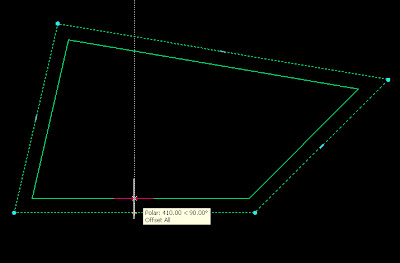
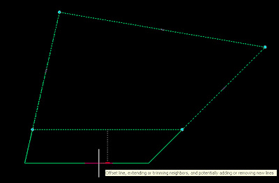
But this is not the only thing we will be able to do. Click Ctrl and instead of ofsetting the edge you will be adding a new vertex.
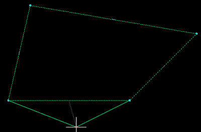
Click Ctrl again and you wil transform that edge into an arc.
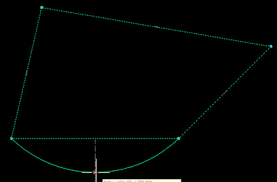

And for a last useful trick, press Ctrl again and you will get to offset all the edgs at a time.


Similar great features will happen if you click contr after selecting one of the vertex grips instead of the egde ones.

- Click the grip to move the vertex

- Press Ctrl once to remove the vertex

- Press Ctrl twice to Offset both edegs that intersect on that vertex.

As a last cool feature of the AEC polygons try to select the middle grip og an AEC polygon with an arc segment. You will also have several options:

- Click the grip to offset the arc segment (it might add some segments to the AEC polygon)

- Press Control Once and you´ll be able to modify the radius of the arc segment

- Press Ctrl again and you will straighten the segment

- Press Ctrl Again and you will add a vertex (and two arc segments)

- Press Ctrl again and you will offset all the faces of the AEC polygon.

I would say that, combined with the AEC modify tools, there is no reason to keep using the polylines.


Show me more...

AutoCAD: Disabling selection preview for Hatches

Do you get stuck in the selection preview of complex objects?A nice feature like the selection preview can become really annoying if we are working with dense hatch patterns.
What selection preview does is that it highlights the object we are going to select if we click the left mouse button. This works very nice and smooth with simple objects like lines, polylines, arcs, etc. It happens though that when we have a dense hatch, specially if it is a hatch made of dots it might take several seconds to show the selection preview due to the amount of objects in the hatch pattern.
Although we can turn off the selection preview turning the SELECTIONPREVIEW system variable to 0, what we actually want to do is to keep it on for some elements and off for some others like hatch patterns.
We have two options to do that.
  1. Set the system variable PREVIEWFILTER to 16, this will only exclude hatch patterns from the selection previews.
  2. Go to Format --> Options --> Selection Tab -->Visual Effects Options --> Advanced Options --> Uncheck the Box in front of Hatch Patterns.
See it in a couple of images for more detailed reference.


Show me more...

AutoCAD: Creating New Palette Group

Organize your blocks on a custom made tool palette.. We might want to create a new Tool Palette Group, let´s say to store all our blocks. The default groups in AutoCAD Architecture 2008 are Design, Document, Detailing and Visualization.
Lets assume that we want to create a new palette group for all the blocks we have.We have to right click on the lower corner of the tool palettes bar and select "Customize Palettes". We will get the following screen.
On the righ portion of the window we right click on a blank portion of the screen and we select "New group". We will name the new group "Blocks". Now to be able to see the new group it needs to have at least one palette. We can drag one palette from one of the default groups to our custom created one.
We click close and right click again the bottom corner of the tool palettes bar. A new line with the name of our group will appear.
Once in the new group we can add as many palettes as we want to it, and drag and drop the blocks to them so they can be easily accessed from any file.
Once we have created our grup and configured our palettes we might want to transfer them to other computers. See this post to know how to do that.


Show me more...

AutoCAD: Transferring Tool Palettes

Transfer your tool palettes from one computer to another.
Català - Castellano
After creating tool palettes in any of the AutoCAD versions, you might want to transfer them to other computers in your network. There is no Export command so finding the way to do so it might be a bit complicated.
Here is a link to the support site from autodesk about the topic. Basically it explains the following steps to do that. You have to use the content browser. But the explanation from autodesk I think is a bit short and might not be enough fo a newby. So here comes a kind of extended version of it.
To store the palettes you have created do the following:
  • Click on the content browser icon or type CONTENTBROWSER in the command line window.
  • Right click and "Add Catalog" --> Create New Catalog
  • Browse to a network location that all computers can access.
  • Save the catalog there.
  • Double click the new catalog that you have created.
  • Drag and drop the new palettes to from you palettes side bar to the Catalog.
In any computer where you want to add those palettes, follow these steps
  • CONTENTBROWSER
  • Add catalog --> Add an existing Catalog
  • Browse t the network location you specified before
  • Double click the new added catalog
  • Drag and drop the palettes you want from the catalog to your tool palettes bar. (see that it is not a simple drag and drop operation, you have to click in the palette you want to load in the contend browser and keep pressing the mouse button till a syringe icon loads, then drag to the tool palettes bar in AutoCAD
Note: After the initial transfer operation, you can add new tool palettes that you created by drag and dropping them to the Catalog in Content Browser. That will make any palette you created in one computer available to the other users on your network.
kick it on CadKicks.com

Show me more...