Easiy draw helixes or spiral curves with this simple plugin.
Català - Castellano - Deutsch
DRAW HELIX (drawhelix13.rb) by Peter Brown allows us to draw helix and spiral curves (flat helix). It is very easy to use and quick. It is accessible via Draw --> Helix (I've modified slightly the original code that was pointing to Draw --> DrawHelix13). It shows a dilog box like the following one, where you can set the different options.
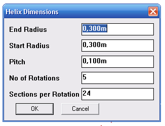
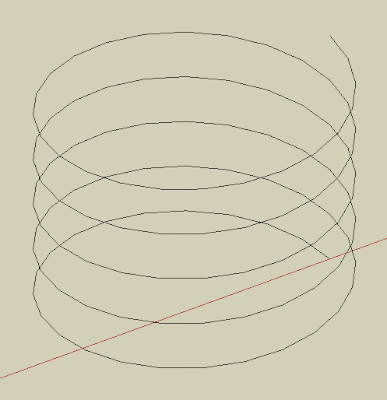
Pitch is the Height of one Helix Rotation. That way, if we set the pitch to 1m and number of rotations to 5, the total heght of the helix will be 5m. The number of segments per rotations will define how many lne segments will form each rotation. This is the result obtained with the default values shown on the image above.
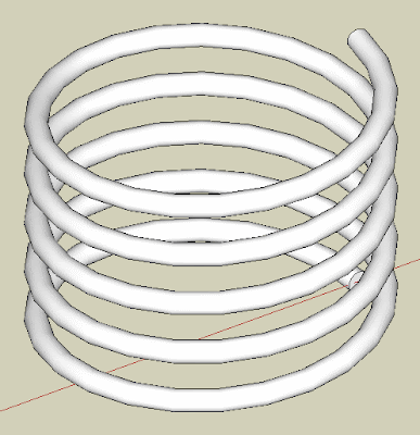
By using a plugin like TUBE ALONG PATH, we are able to turn the helix line generated to a rederable helix.
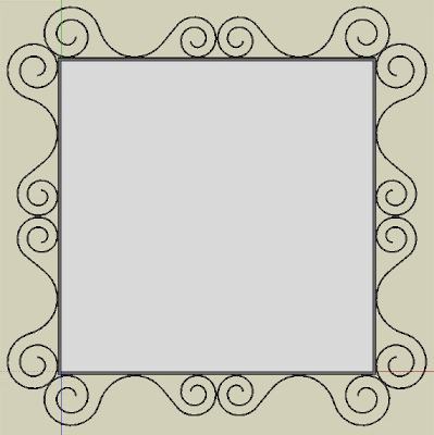
If we want to draw spirals (a flat helix of changing radius) we simply need to set the Pitch to 0. See how I modeled my ugly living room mirror ;).
Chek here how to Install SketchUp Plugins.
Show me more...
Maxwell Render: New 2.0 Version Coming Soon
Check out the new features of the upcoming version 2.0 of Maxwell Render.
Català - Castellano - Deutsch
Next Limit is announcing on their website the new features of the soon to be released Maxwell render Version 2. The website has plenty of examples of the improved features comparing them to the latest released version v1.7.
So far, for what I've seen on the website, the speed improvement (one of the weak points of Maxwell has always been speed) is amazing, and the behavior of light sources has also been tremendously improved.
I can't wait for the release of this new version and find out about all the new features.
Show me more...
AutoCAD: Use Curved Frames to Clip your References
Clip your Blocks or XREFs using curved polylines, circles, etc
Català - Castellano - Deutsch
A common problem found when using the XCLIP command is that it doesn't clip properly if the polyline we use has curved segments. The same way we can't use circles to clip Blocks or XREFs. If you try to clip a block using a polyline that contains curved segments you will see that along the curved segment the clipping is not done properly. See the following image. The block was clipped using the yellow polyline. The result is not satisfactory at all.
The first image shows the original block, the second one is the block clipped with the XCLIP command. As you see we need a work around this result. The work around is to use an Express Tool Command.
CLIPIT is an express tool command that will allow us to do what we wanted to do. CLIPIT will ask us to select the new clipping frame, that can actually be a POLYLINE, CIRCLE, ARC, ELLIPSE, or TEXT object. It works the opposite as the XCLIP command. With CLIPIT you first select the frame and then the Block, Image, Wipeout or XREF you want to clip. See the following image with the result.
What CLIPIT does, is turn the curved clipping frame into a set of segments. If you switch on the XCLIPFRAME and select the block, you will see that the frame is actually made of straight lines. See it below.
The only bad part of this express tool, is that so far (till version 2009) it doesn't allow inverted clips. We talked about how useful inverted XCLIPS can be on a previous post. Hopefully in future versions of AutoCAD this will be solved.
Show me more...
Labels:
AutoCAD,
Blocks,
Express Tools,
XREFs
AutoCAD: Select all Connected Geometry.
Wonder how to select with a single click all connected geometry? AutoCAD can do it, you just need to know the right command.
Català - Castellano - Deutsch
Usually my day at work involves designing and drawing both in AutoCAD and SketchUp (and eventually in Rhino depending on the complexity of the geometry of the project). Switching back and forth from one software to another makes you miss on one program some of the functions that the other program has. This was the case of the "Select all Connected" option in SketchUp. It is so useful to select all connected geometry (it can be accessed through a right click menu or by triple clicking any line on the drawing). But can something similar be done in AutoCAD? The answer is yes.
There is an Express Tool for AutoCAD called FASTSEL (accessible also via the FS shortcut) that allows us to select all the geometry that is connected (touching) any element on our drawing. The elements that can be used using this commands are LINE, POLYLINE, LWPOLYLINE, CIRCLE, ARC, ATTDEF, TEXT, MTEXT, ELLIPSE, SPLINE or IMAGE objects. BLOCKS or XREFs containing these objects will also work.
AEC Objects from some of the vertical products such as Walls or AEC Polygons are not supported. In case you have a Block or XREF containing both supported and unsupported elements, the command will only use the supported elements.
The command can be accessed transparently while using other commands by typing 'FS while the command is running. Also, use the FSMODE System Variable to control if the FS command selects all connected geometry (FSMODE = ON) or only the geometry connected to the first object (FSMODE = OFF).
Note that this Express Tool Command is mostly intended for 2D since I tried to use it in 3D and lines that are actually not touching other geometry did get connected. I find it specially useful when I accidentally explode polylines, with this command you can select all the lines that where previously connected with a single click. Select faster than a private jet with this express tool!
Show me more...
Labels:
AutoCAD,
Express Tools,
System Variables
SketchUp Plugins: Slice Your Model
Do you need to get slices of your SketchUp model to build a real life model? Slice it easily with this Plugin.
Català - Castellano - Deutsch
A common process in my office is to design some of the buildings in SketchUp and then build physical models of them cutting the pieces with a laser machine. With simple geometry this is no problem, and it is easy to draw the outlines of the pieces in AutoCAD to send them to the laser cutter. When the Gemoetry is more complex the process requires a bit more effort.
SLICER (slicer.rb) is a Plugin that helps doing this. The Plugin generates slices from a given 3D model and you can choose which axis you want to use for the slices to be generated.
See the following example. I used the same terrain I used on a previous post and I created slices of it every 5m.
The plugin even asks you if you want a flattened copy of your slices, which basically means that it will spread the slices on the ground plane, so you can just set a Top view and Export to AutoCAD. See the image of this other simpler model.
Of course CAD exports from SketchUp are not always very clean, so there might be some tweaking needed before using a laser cutter, but this definitely speeds up the process. To use the plugin, select a Group or Component, go to Plugins --> Slicer and then use the dialog box to configure how the slices should be created. Download the Plugin here.
Chek here how to Install SketchUp Plugins.
Show me more...
AutoCAD: Delete a Layer that Contains Objects
Do you need to delete a layer but the purge command doesn't do it? No worries, there is an express tool for that.
Català - Castellano - Deutsch
One more day of problem solving at work. Ryan asked me today if I knew how to delete a layer that the purge command doesn't delete. The solution is to use one of the Layer Express Tools. And of course I thought: let's write about it here during my lunch break! It is raining anyways.
LAYDEL is an Express Tools Command that allows us to delete a layer even if it contains objects. This is useful to delete layers we want to purge but because they might be included in some block definition we are not using anymore, the purge command can't delete them. Be careful though, since it will delete the layer and its contents. TO use it simply make sure that the layer you want to delete is not current, type LAYDEL and select an object on that layer (alternatively you can access this function through Format --> Layer Tools --> Layer Delete).
There is an alternative method to delete a layer but keep its objects. The LAYMRG Express Tool Command merges one layer into another and deletes the first one. It is very useful when trying to simplify the layer structure of a drawing but we want to keep all its graphical information. To use it, type LAYMRG (alternatively you can access this function through Format --> Layer Tools --> Layer Merge)select the layer to delete and merge, press ENTER, then select the target layer where you want the information to be merged to.
Show me more...
Labels:
AutoCAD,
Express Tools,
Layers
SketchUp: Load new Plugins without Restarting the Program
Do you want to load a new Plugin without restarting SketchUp? Alex Schreyer has a Plugin for that.
Català - Castellano - Deutsch
Sometimes we want to try new Plugins we just downloaded without the "hassle" of closing SketchUp and opening it againg. Alex Schreyer, has written a Ruby Script that allows us to do that.
PLUGIN LOADER (as_pluginloader.rb) adds a submenu to the plugin menu that allows us to reload the entire Plugins folder or to pick one by one which Plugins we want to load.
You can download the plugin using the above link or go to Alex Schreyer Website were he keeps updating it with the latest release.
Show me more...
AutoCAD: Offset Ellipses and keep them as Ellipses
Tired of getting SPLINES when you offset you ellipses? Maybe you want to try this quick video tutorial.
Català - Castellano - Deutsch
One of the biggest issues of working with ellipses is the fact that if we offset them using the OFFSET command, they become Splines. Splines are entities that are hard to work with, especially when we need to trim parts and later we want to extend them again. Tired of toggling the PELLISPE system variable many times, i wanted to see if there was a way to offset an ellipse but keep it as an ellipse. I did found the way to do it. It is a bit slower than using the OFFSET command, but if you think you might need to edit the resulting ellipse maybe you want to give it a try. See the video below.
The steps are simple:
Show me more...
Català - Castellano - Deutsch
One of the biggest issues of working with ellipses is the fact that if we offset them using the OFFSET command, they become Splines. Splines are entities that are hard to work with, especially when we need to trim parts and later we want to extend them again. Tired of toggling the PELLISPE system variable many times, i wanted to see if there was a way to offset an ellipse but keep it as an ellipse. I did found the way to do it. It is a bit slower than using the OFFSET command, but if you think you might need to edit the resulting ellipse maybe you want to give it a try. See the video below.
The steps are simple:
- Draw two lines from the quadrants of the ellipse. Their length should be the distance you want to offset the ellipse. (To be able to Snap on the qadrants, turn them or access the quadrant osnap with through the OSNAP contextual menu)
- Select the ellipse, move one of the grips next to one of the lines to the other end point of that line while holding the CTRL key.
- Move the grip next to the other line you previously draw to the other endpoint of the line
Show me more...
SketchUp Plugins: Color Terrain to Show Terrain Slope or Height
Need to see which are the high points of your terrain or which areas are too steep to build on? Use thses next two plugins to quickly see that.
Català - Castellano - Deutsch
Chris Fullmer published some time ago a couple of plugins to Color Models according to the Height or the Angle of the faces. This turns to be very useful in many situations. I came across these Plugins because we were planning a new development and needed to easily visualize in plan which where the high points and were we had too steep areas.
COLOR BY Z (clf_color_by_z): Colors faces according to their height (z value). you can pick which color you want to be the one for the highest point, and which one you want for the lowest point. It will create a gradient from one color to the other. See the images below.
COLOR BY SLOPE (clf_color_by_slope): Does the same trick, but coloring the faces according to its angle (slope).
See these next two Plan shots to understand how this could be useful to you to identify potentially bad areas to build or to simply glimpse the height changes of your terrain in plan.
Show me more...
Autodesk Announces Support for MAC Boot Camp Users
One step closer to be able to use AutoCAD on your Mac 100% hassle free.
Català - Castellano - Deutsch
Autodesk has a website were it announces support for Boot Camp Mac users. This doesn't mean you will be able to run AutoCAD on your MAC OS, you still need bootcamp, but at least now Autodesk is making sure AutoCAD (and other products such as 3Dmax, Inventor and Revit) run properly on Boot Camp. I can't tell if the rumors of a deal between Autodesk and Apple to have a MAC version of AutoCAD are true (I've read numerous posts about it) but at least this is little step forward.
Show me more...
Labels:
AutoCAD
SketchUp: How to Install Plugins
What you need to know to install and find Google SketchUp Plugins
Català - Castellano - Deutsch
SketchUp Plugins, also referred to as Ruby Scripts, are pieces of Ruby code intended to extend the functionality of SketchUp. How to install SketchUp Plugins ? You simply need to copy them into the Plugins Folder of SketchUp and restart the program (or use the Plugin loader as-pluginloader.rb). By default the plugins folder is located under
C:\Program Files\Google\Google SketchUp 7\Plugins. (Windows)
or
Macintosh HD/Library/Application Support/Google SketchUp 7/SketchUp/ (Mac)
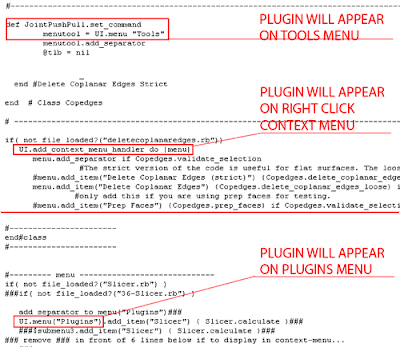
Once you've done this, the plugin will appear in one of the menus. Be sure to check both the Plugins Menu, and the Tools menu. Many developers prefer to put their plugins into the Tools menu instead of Plugins, this is the case for plugins such as Joint Push Pull, Make Faces, and many others. So be sure that you check all the menus because the new feature might be in some other menu that is not the Plugins menu. There are even some plugins that end up on the View menu, like PageExIm.rb and some others.
If you want to be sure of which Menu the plugin should appear in, you can open the .rb script file and check its description. Many developers include in the beginning of the script some comments that explain how to use or where to find the script. If those comments are missing, scroll down to the bottom of the code and you will find a string of code like these ones.
Show me more...
AutoCAD: Use the autosave files to recover your work
Make sure you activate the autosave option and see where to recover the files from.
Català - Castellano - Deutsch
We had an awful day at work today with lots of FATAL ERROR crashes, probably due to some circular references on the XREFs. Some of the files ended up being completely unrecoverable so we had to find the most updated backup files we could find. This made me write an e-mail to everyone explaining how to find and use the backup files that are created with the auto save option in AutoCAD.
Although for "light" crashes, these files can be accessed through the recovery wizard, this was not our case, so it was a question of searching and finding those auto-save files to replace the corrupted ones. I thought I'd share here that information in case someone doesn't know about the auto-save feature and how o locate those files.
1. Go to Tools --> Options
2. Inside Options go to the “Files” Tab (far left)
3. Inside the files tab go to: “Automatic Save File Location” and see where the autosave files are stored. (mine where stored at C:\Documents and Settings\USERNAME\Local Settings\Temp)
4. Then access that folder and try to find a file with the same file name but different extension. (The autosave files should have a either a .BAK or a .SV$ extension) (if you can’t see the folder, you need to go to Tools --> folder Options --> View --> and Make sure "show hidden files and folders" is SELECTED) .
5. Check the "date modified" of those files, if the date and time makes sense according to when you had the last file crshes, there is a good chance that those files contain the information you need, so there is no need to redraw everything.
6. Change the file extension of the file you think it might be the good one from .bak or .sv$ to .dwg (to be able to change the file extension you need to be able to see it. To do that, on any folder go to Tools --> Folder Options --> View --> and make sure that "Hide extensions for known file types" is UNCHECKED)
If your auto-save feature is disabled, you can enable it in AutoCAD by going to Tools --> Options --> "Open and Save" Tab --> and there make sure that the "Automatic save" on the lower left corner is active and preferably set to every 10 minutes or less. To easily change the time of the autosave feature, use the SAVETIME system variable (this last tip thanks to lazydrafter)
Hope this helps, it saved me 2 hours of work. Using it properly is like having good car insurance. You never know when you'll need it!
Show me more...
Labels:
AutoCAD
Subscribe to:
Posts (Atom)