AutoCAD: Save All The Open Drawings

An Express Tool command allows you to save changes on all open drawings.
Català - Castellano - Deutsch
The Express Tool Command SAVEALL allows you to easily save changes on all open drawings, no matter if you have only one drawing open or you have 15 of them open.
This, as simple as it sounds can be useful when for whatever reason we are working simultaneously on many drawings updating all of them. With this command, we can save changes on all the drawings in a very simple way.
Similar to this command is the CLOSEALL Express Tool command. What this one does is to close all the open drawings asking if you want to save changes in those that have been modified. So next time you need to save and close a lot of drawings, you can simply type SAVEALL and then CLOSEALL and all the drawings will be saved and closed in only a few seconds.


Show me more...

AutoCAD: Draw Walls Using the MLINE command

Plain AutoCAD can draw walls too. You Just need to learn how.
Català - Castellano - Deutsch
AutoCAD has a pretty unknown command called MLINE that allows you to draw Multilines. Multilines are ideal for drawing walls in plain AutoCAD. You simply need to create the wall style through the MLSTYLE dialog Box and then draw the wall as you would draw a line. See the dialog box.


And a MLINE I created to represent ta wall section.


MLINE Objects do not cleanup automatically with each other like AutoCAD Architecture Walls. There is a dialog box accessible via right clicking an MLINE and selecting Multiline Edit or simply typing the command MLEDIT that will let you choose how do you want the Multilines to join/cleanup between each other. This is the dialog box.


An this is how from an uncleaned intersection between two MLINEs.


You can get a nice cleanup, in this case using the Merged T intersection.


See that to create this multiline wall I used a special linetype to represent the Insulation. You can get it for a small Paypal payment. (email delivery)


Show me more...

AutoCAD: List of 2D Objects

A complete and Organized list of the AutoCAD 2D Objects and links to those explained in CAD Addict.
Català - Castellano - Deutsch
There are many different types of Objects in AutoCAD. On an effort to keep updating the directory of CAD-Addict.com here comes a complete list of the 2D Objects and the links to those articles that explain their use. I will try to keep adding lists of objects weekly and at the end I will create a post that works as a main directory for this series of posts.
2D Objects

There are 2D objects that are created through other commands, but regardless when created they are in one of these categories. An example of this would be Polygons, Rectangles or Donuts which are actually Polylines.

Show me more...
Photoshop: Access a Wide Range of Text Editing Tools

There are many more options to edit Text than you think in Photoshop. You just need to know how to access them.
Català - Castellano - Deutsch
This is one of this tips that some might think "duh!", so I excuse myself in advance for my lack of Photoshop proficiency. But since this website is as much a way for me to share what I learn, as a way to store tips for when I need them and I can't remember here it goes.
When you type texts in Photoshop, the default options available are pretty limited, all contained on the upper toolbar that looks like this (the screenshot is from version CS4).


But if you click on the button on the far right of this toolbar, you will be able to access a full set of tools to edit your texts much more complete that the default text toolbar. Alternatively, this Character Window, can be accessed through Window --> Character (duh again, I know...). On this window you will be able to use Sub- and Superindex characters, use Title Fonts, play with the font spacing etc.


Maybe for many this is the kind of tip that you wonder "how could this guy not know about that?". I know it is a very basic tip, but it is a tip anyway.


Show me more...
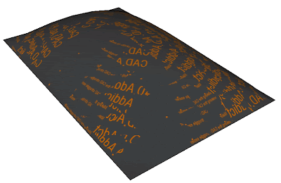
2008 Posts of the Month

The most visited posts of 2008 by month.
Català - Castellano - Deutsch
I am trying to organize my site a little bit and will try to come with some posts that work as a directory of it. To shorten the list of "most visited posts" on the sidebar, here comes the list of the most visited posts of the months between June and December 2008. This is just a way to make old posts accessible to those who joined CAD Addict recently. Hope you find something interesting. This is the list.

See that the list starts on June 2008 since it is when I started using a visitor tracking service.

Show me more...

Mastering AutoCAD Architecture

Become a Pro of AutoCAD Architecture with this book.
Català - Castellano - Deutsch
Jason left our office last week and he gave me his "Mastering AutoCAD Architecture Book" by Paul F. Aubin as a farewell present. I've been browsing through it and it seems I am gonna get some nice tips to post here.
The book is divided in 18 Chapters plus several Appendix with extra exercises. The language is clear and concise and it seems to go to the point right away. Tips like "in case of doubt, right click" can give you an idea of the type of plain and direct language used. I've got the edition for the 2008 version of ACA "Mastering AutoCAD Architecture 2008". For those looking for the latest version of the book follow the links below.


or or


Show me more...

SketchUp: Apply an Image to a Curved Surface

How to use an imatge as a texture and be sure it is sized properly?
Català - Castellano - Deutsch
Many times we just used plain paint materials in SketchUp, but other times we need to use images as textures. Applying images as materials is a simple process, but there are certain things that are important to know to apply them the way we want to.
If we simply want to see the image on a flat surface in SketchUp, we can skip using the image as a material and simply import the image as such. For that, simply go to File --> Import and select the image you want to place. You will be able to place it as an object.
If we want to apply the image onto a curved surface, the thing becomes a bit more tricky. To do this, we have to turn the image into a material. Follow these steps to do it properly.
  1. File --> Import the image.
  2. Resize it to be the right size you want it to be projected
  3. Right click on it and explode it
  4. Click on the Sample Paint tool in the materials browser and click on the exploded image
  5. Enter the group or component containing the curved surface and apply the material to it.

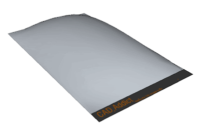
Let see this process graphically. Point 1 and 2. After importing the image, we place it and size it to the position we want it projected. IN this case, I am trying to paint the below curved surface created with Soap Skin Bubble and the Soften Edges Tool with the CAD-Addict website header. I align the image to fit exactly with the surface width. See below.


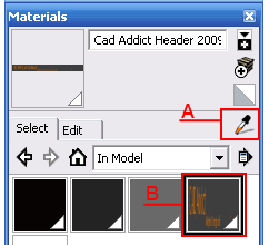
After the image is placed properly, we need to explode it. Right click on it and select Explode. This will add the image as a material with the right size and position. We can select the material using the Sample Tool (A in the picture below) or simply browse the "in Model" materials in the material browser and find the thumbnail that corresponds to the new material created from the image (B in the picture below).


After this, we simply enter the component select the surface and apply the material. The result should be something like this.


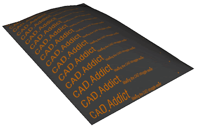
It is very important that we enter the component or group and apply the material directly to the curved surface, if instead of that we apply the material to the component (being outside of it), SkechUp will not recognized the softened surface as one and will apply the image to each and every face of the object, making it look like this.


Show me more...

SketchUp Plugins: Create Custom Windows / Curtain Walls

Easily create Windows with a Plugin that works as good as windowizer but that will do any window shape or custom design.
Català - Castellano - Deutsch
I wrote not so long ago about Rick Wilson´s Windowizer Plugin to create Windows from a face. Windowizer is great, but it only creates windows based on a regular grid (number of rows - number of columns).
TIG's Latticeizer (Laticeizer.rb) does what Windowizer 3.0 can't. It creates a window with it's mullions and glass parts from a series of faces, cleaning up the intersections very neatly. See how from this set of faces (all faces have to be coplanar) i easily created a custom window.


All faces need to be coplanar and need to be Grouped. The dialog Box will let yo choose the settings, sizes, colors, etc. Pretty Cool. Thanks TIG!!


Download the Plugin Here.

Show me more...

AutoCAD Express Tools: Replace Blocks

Replace all the instances of a Block for a different one with this express tools.
Català - Castellano - Deutsch
I use quite often simple Blocks as placeholders for parts of the drawing that might change or get more detailed in the future. This might apply to windows, doors, toilets, staircases,etc. We might want to put a placeholder to have a rough idea of the space needed for those objects, and later on we might want to replace that placeholder for the final and more detailed block. How do we do that in a simple and fast way?
We use the BLOCKREPLACE express tool. With this command, we can easily pick the block we want to replace and the Block that will replace it. When we enter the command, we will get the following dialog box, where we enter the name of the block to be replaced. If we don't remember the name, we can simply press the pick button and select the block on the screen.


After selection the block to replace, the same dialog will ask us for the block we want to use as a replacement. For this command to be effective, we must have two blocks that have their 0,0,0 coordinate (their insertion point) at the same location, and not be rotated differently. Otherwise, the new blocks will not show in the proper location or with the proper rotation.


Show me more...

SketchUp: Site Design - Randomizing Vegetation

How do you randomize the scale and rotation of a series of objects? Wiht one of Chris Fullmer's Plugins!
Català - Castellano - Deutsch
On my recent post about site design, we saw how to easily place trees on site using the Drop plugin.
Once those trees where placed I found myself wanting them to be a bit more random. I didn't like the fact that all of them where the same size. The intention was to ebable to Select them all and turn them into randomly scaled-rotated copies. So I asked at the Sketchucation Forums, and I got the answer to my wishes.
Chris Fullmer's SCALE ROTATE MULTIPLE (clf_scale_rotate_multiple.rb) does exactly that. You simply select a set ob objects, and run the plugin through Plugins --> Chris Fullmer Tools --> Scale and Rotate Multiple --> Scale and Rotate All Randomly. On the dialog box you set the paramaters of maxim and minimum scale and maximum and minimum rotation and that's it. See how the All equal trees on the first image become randomly scaled on the second one.

IN this case the rotation doesn't matter because of the simplicity of the tree component, but if I ever replace it with a more complex/realistic tree, the instances will be also randomly rotated.
To download the Plugin and to see a quick explanation video, go to the Sketchucation original thread (need to be registered to download)


Show me more...

AutoCAD: Breakline and Dimjogline

Draw the breakline symbol and dimension elements that contain this symbol properly
Català - Castellano - Deutsch
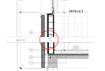
When doing detailed sections and other similar drawings, we tend to not draw the entire length of a facade. Rather, we detail certain parts and represent them in a sequence. To separate those different parts we use the break line symbol. This symbols also used on floor plans to represent the point where the stair intersects with the cut plane of the floor plan (at school they always told us to consider 1.5m as the cutting plane for floor plans)
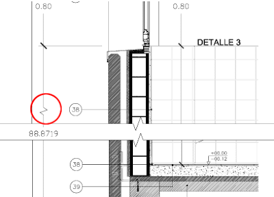
AutoCAD has an express tool to draw the break line symbol, no big secret. Simply enter BREAKLINE or go to Express --> Draw --> Break-Line Symbol. You will enter the 2 points you want the break-line symbol to reach, and the third point you pick is where the jogged line will appear. See how in the detail below, 2 break line symbols have been used to separate the different parts of the detail.


If there is an element that we want to dimension that gets cut by this break line, we might want to represent the dimension symbol with a jogged line too, so whoever reads the drawing understands that the dimension shown is the real dimension not considering that we have cut part of the drawing for representation purposes. To do this, we need to use the command DIMJOGLINE, that will allow us to add the jog line to an existing dimension. The result being something like this.


Show me more...
SketchUp. Adding Text to Dimensions and Keeping them Dynamic

Add descriptive text to your dimensions without breaking the capacity of these to get updated dynamically
Català - Castellano - Deutsch
From the official Google SketchUp Blog we get this tip on how to add text to dimensions and keep them dynamic. Once we have placed a dimension, this will update if the objects link to it move. When we add the text, the dimension will not update anymore unless we do this.


The trick is simple, once you added the text, replace the dimension value for <>.This will show your text and the dynamic dimension near it. If you want to have a line break (windows only) add this \n where you want the line break to happen.


Show me more...