How do you hide and/or unhide walls or other objects
Català - Castellano - Deutsch
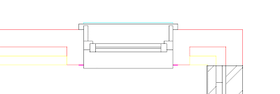
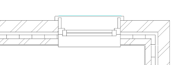
I wanted to hide a wall to be able to see the imported linework below. This took no effort to find out. Simply select the element you want to hide, right click and select Hide --> Element on the right click menu. (it can also be accessed via Ribbon)
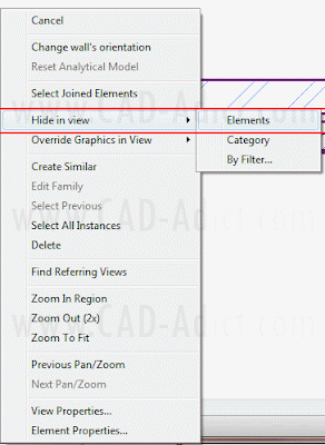
See the Element i wanted to Hide, the Wall, and once hidden how I can see the linework imported.
To Unhide Wall, Windows or any other Elements Hidden we need to activate the "Reveal Hidden Elements Button. It is on the lower left of the view.
This will alow us to enter the Hidden Element Reveal interface, where hidden Elements are shown in Redish color and others are faded in Grey.
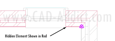
Then selecting the element and using the right click menu, or using the button on the ribbon, we can unhide them.
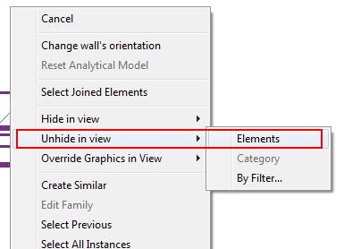
The same procedure can be done hiding elements by category instead of single ones, or using filters. We will see that on another post.
Show me more...
Revit Basics: Control the level of Detail of a View
Set how detailed you want a view to be.
Català - Castellano - Deutsch
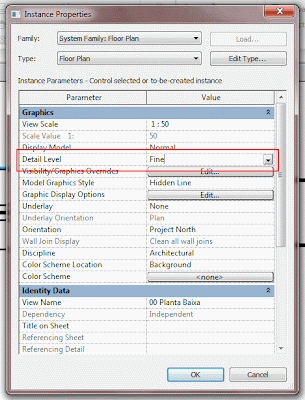
If you can't see all Layers, Parts of your model, this might probably be because your Level of Detail is not set to "Fine". To change the Level of Detail (LoD), go to the View Tab --> Graphics --> View Properties (See below).
There, go to Detail Level and set it to Fine. (See below)
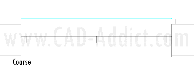
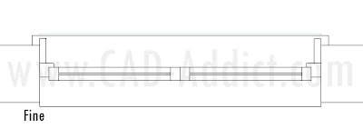
This is a useful feature that allows us to control how detailed is the model shown. I assume there is a reduction on speed by setting it to Fine, so I guess we must be careful if working with big models. Coarse is the less detailed level, and fine is the more detailed. See below the three Detail Levels for a Window.
Show me more...
Revit Basics: How to Switch Off Lineweight Display
How can you switch off the display of Lineweights in Revit?
Català - Castellano - Deutsch
The time has arrived! My first revit Post. I've been "fighting" with the interface a bit these past fewdays. One of the first things I had to solve was to find how to switch off the lineweights to be able to work with better precision. It didn't take me long, and i know this is probably not even Revit 101, so forgive me for how basic this might sound, but just in case there is someone starting to play with Revit too, here comes the Tip.
You can switch off the Lineweight display by using the View Tab of the Ribbon and going to the far left on "Graphics" and pressing the ThinLine button. Alternatively, and if you are an AutoCAD user you might prefer this, you can simply type TL. A difference between Revit and AutoCAD is that we don't need to press ENTER to use keyboard shortcuts.
I am struggling a bit getting used to the Interface but specially to the fact that I am not drawing lines anymore but modelling a Building, so no cheating seems to be allowed. Good, motivation is there, so hopefully I'll share more useful tips about Revit soon. For now probably very basic, but it is about time!
Show me more...
Free Online Generic BIM Object Library #02
Trying to find free BIM Objects online? Here comes resource number 02
Català - Castellano - Deutsch
RevitCity.com has a very nice set of Families for Revit. What is even nicer is that they have their library organized using the CSI Master Format, so if you know this Format, all objects will be easy to find by they number.
As many of these online libraries their strenght is sometimes their biggest flaw. It contains a great number of Families, but this, can become a problem when searching for some content.
One of the big challenges using Revit that I found so far, is the need to have the right families (quality and quantity). Otherwise, any time you want to place a window or a door, there are so many families to consider that you do not consider it at all. Of course, a BIM Model requires to get more detailed as project phases advance, but beeing able to see what you are doing directly in 3D, makes it kind of hard to leave an ugly door in the model as a placeholder.
I guess I am still too much on the CAD side where a window or a door are just symbols that will be described later, but I definetily find this challenging. How many manufacturers are distributing Families/Components of their products as they use to do with CAD Blocks/Cells?
Show me more...
SketchUp Plugins: Extrude Edges by Face
Extrude any face along a path. it sound like Follow Me tool? Well it is much better and faster.
Català - Castellano - Deutsch
TIG set of Extrusion Tools is great. Another Tool of this set I wanted to show you here is the ExtrudeEdgesByFace.rb. This one allows you to Extrude a face following a line or set of lines (straight or curved). I know this might sound exactly as the Follow me Tool, but it is not. The advantages compared to the Follow Me Tool is that the Face doesn't need to be properly alligned with the profile to be extruded properly. See these two images.
If you want, you can rotate the face and use the Plugin again and the result would be this one.
Another advantage of this Plugin compared to the Follow me Tool is that it allows you to do multiple Extrude Operations at the same time. Like the one below. I selected the Face and all the paths, and in a single operation i got this result.
The Plugin is part of the Extrusion Tools by TIG. You can download them here.
If you are new to SketchUp chek here to know how to Install SketchUp Plugins.
Show me more...
AutoCAD: Manage Layers with the LAYWALK command
Manage layers in a simpler way than using the Layer Manager
Català - Castellano - Deutsch
Even from the colleagues that know less about a program you can learn something new. This happened today at work. I was asked some very simple questions about AutoCAD commands. Siting near my colleague to teach him how to do things, I realised he was using a command I didn't know and that is quite useful.
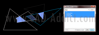
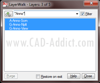
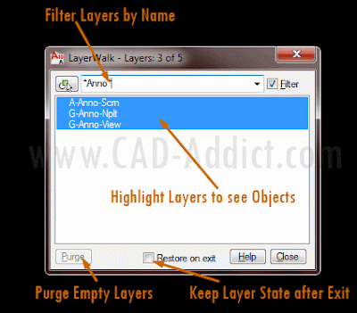
LAYWALK, is a command that allows us to handle Layers very nicely. It opens a dialog where we can see all the layers listed. The objects on the highlighted layers will be shown on the screen.
In case we have a lot of layers we can use the filter bar to only show the ones we want. Use * in front and/or after the text to include all layers with that text in it.
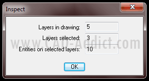
Selecting a layer or several layers and doing "Right Click --> Inspect" will show us some information about the layers and the amount of objects contained.
If there is any layer without any objects, we would be able to purge directly from here using the purge button. We have also the option to "resotre on exit" or not. If restore on exit is active, it means that when we close the LAYWALK window, the layer state will go back to how it was before running the command, if we uncheck this option, the layers will stay as we set them in the LAYWALK window. See a summary of fucntions below (click to enlarge).
Very useful command to manage layers and much faster (although with less functionalities) than the Layer Manager.
Show me more...
AutoCAD or AutoCAD Architecture??
How many of you are still using plain AutoCAD? Try to move to AutoCAD Architecture at least, you'll work much much faster.
Català - Castellano - Deutsch
I've been recently struggling with the experience of working with plain AutoCAD after 3 years of working with AutoCAD Architecture in a professional environment. It is hard for me to understand (other than pure commercial strategy) why plain AutoCAD still exists.It might sound weird if you are working with plain AutoCAD, but once you've tried AutoCAD Architecture, plain AutoCAD feels like someone has cut one of your arms.
The tools I miss the most are the AEC Modify Tools (see them in this post) accessible via right click context menu. Other functions that are not available and that really speed up the work are the "Select Similar" and "Add selected". Select Similar allows us to select all similar objects 8same type, layer,etc) directly from the right click context menu too. And Add Selected allows us to add an object that is the same as one selected, saving tons of time on remembering commands.
These last two functions are available in AutoCAD if you have a Subscription Advantage Pack. Here is the Autodesk page that showcases these functions. But you should know, and this is the main reason I write this post, that these functions are available in AutoCAD Architecture, so to mee, no point paying for some functions, when you could have them all.
Also, considering that the transfer to BIM will happen sooner or later, consider next time you want to upgrade , to go for the AutoCAD Revit Architecture Suite. This one contains AutoCAD + AutoCAD Architecture + Revit Architecture.
So just to wrap up and up to my own curiosity to know what my readers use every day. Could you answer this poll? What program do you use every day at work?
Thanks!
Show me more...
Labels:
AutoCAD,
AutoCAD Arch
SketchUp Plugins: Extrude Edges by Loft
A powerful Plugin to create a "Loft Surface" between curves.
Català - Castellano - Deutsch
Not so long ago, we saw the Loft Plugin by Chris Fullmer that allowed us to create Lofts between curved edges. Although the Plugin was useful, it had some imprecisions and not so much functionality.
TIG, inspired by this Plugin, has created the extrudeEdgesByLoft.rb Plugin. It is, for its functionality, like a much better version of the previous Plugin by Chris Fullmer. It creates the Loft surface with better precision from given curves, see below.
Besides creating the mesh, it allows you to choose if you want to reverse faces or soften the edges.
And even if you want to eliminate the edges you used to create the loft operation.
Another Great Plugin by TIG. It can be downloaded here (you need to be registered)together with other Extrude Tools that we will soon see here.
Chek here how to Install SketchUp Plugins.
Show me more...
Barcelona in 3D on Google Earth
My hometown is oficially launched in 3D in Google Earth. Go visit it.
Català - Castellano - Deutsch
I normally don't repost this things, but being my hometown I couldn't skip it. Barcelona is officially launched as a 3D city in Google Earth. Go see it. It's worth it. Here a brief video. Unfortunately we've been stereotyped again with some "flamenco-like" spanish guitar song. What can i say, this is not us, but in any case, and as we say in Catalan: Benvinguts a Barcelona!! (Welcome to Barcelona).
via Official Sketchup Blog.
Show me more...
Labels:
Google Earth,
Videos
SketchUp Plugins: Extrude with Rotation
Extrude Edges or faces with a rotation.
Català - Castellano - Deutsch
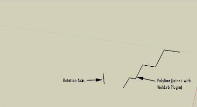
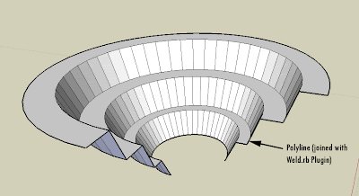
ExtrudeEdgesByLathe.rb by TIG allows us to Extrude Polylines or Faces following a circular path defined by an axis and a rotation angle. The Plugin is part of a suite of several Extrusion Plugins by the same Author that can be found here. The Plugin Allows you to do the following.
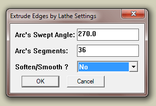
We can set all the properties of the extrusion on a dialog box that appears after we run the Plugin. These are the options for the previous example.
And if we select a face instead of a polyline, the plugin works too!!
Chek here how to Install SketchUp Plugins.
Show me more...
List of BIM Software & Providers
There are a lot of choices on BIM software, see a list here
Català - Castellano - Deutsch
Although BIM is relatively new, it is also a trend that is penetrating the Construction industry fast and I would even dare to say, with no way back. For those trying to choose an application, here comes a comprehensive list of BIM providers for the different categories.
Architecture
I am sure I am missing some, so please add a comment if you know any other. The category order is kind of in the timeline of a building lifespan (Design --> Build --> Mantain). The order of software systems in each category has no reason, first that came to my mind or that I found was first on the list. I know that some of the Systems are more liek add ons to some BIM programs or Analysis Systems. nevertheless, I think these add-on and analysis packages are an integral part of the BIM process and so must be listed together with "pure" BIM modelling tools.
Please Contribute with your knowledge commenting on this post!
Show me more...
Català - Castellano - Deutsch
Although BIM is relatively new, it is also a trend that is penetrating the Construction industry fast and I would even dare to say, with no way back. For those trying to choose an application, here comes a comprehensive list of BIM providers for the different categories.
Architecture
- Autodesk Revit Architecture
- Graphisoft ArchiCAD
- Nemetschek Allplan Architecture
- Gehry Technologies - Digital Project Designer
- Nemetschek Vectorworks Architect
- Bentley Architecture
- 4MSA IDEA Architectural Design (IntelliCAD)
- CADSoft Envisioneer
- Softtech Spirit
- RhinoBIM (BETA)
- Autodesk Ecotect Analysis
- Autodesk Green Building Studio
- Graphisoft EcoDesigner
- IES Solutions Virtual Environment VE-Pro
- Bentley Tas Simulator
- Bentley Hevacomp
- DesignBuilder
- Autodesk Revit Structure
- Bentley Structural Modeler
- Bentley RAM, STAAD and ProSteel
- Tekla Structures
- CypeCAD
- Graytec Advance Design
- StructureSoft Metal Wood Framer
- Nemetschek Scia
- 4MSA Strad and Steel
- Autodesk Robot Structural Analysis
- Autodesk Revit MEP
- Bentley Hevacomp Mechanical Designer
- 4MSA FineHVAC + FineLIFT + FineELEC + FineSANI
- Gehry Technologies - Digital Project MEP Systems Routing
- CADMEP (CADduct / CADmech)
- Autodesk Navisworks
- Solibri Model Checker
- Vico Office Suite
- Vela Field BIM
- Bentley ConstrucSim
- Tekla BIMSight
- Glue (by Horizontal Systems)
- Synchro Professional
- Innovaya
I am sure I am missing some, so please add a comment if you know any other. The category order is kind of in the timeline of a building lifespan (Design --> Build --> Mantain). The order of software systems in each category has no reason, first that came to my mind or that I found was first on the list. I know that some of the Systems are more liek add ons to some BIM programs or Analysis Systems. nevertheless, I think these add-on and analysis packages are an integral part of the BIM process and so must be listed together with "pure" BIM modelling tools.
Please Contribute with your knowledge commenting on this post!
Show me more...
Labels:
BIM
From CAD to BIM: Part II - From CAD 2D to CAD 4D
The transition from 2D CAD to 4D CAD that changed the way architecture is nowadays.
Català - Castellano - Deutsch
Go to Part I
The Adoption of CAD software in Architecture firms was progressive, (I am still trying to find some information on a more or less exact timeline of CAD implementation in Architecture Firms) and it is nowadays widely spread in virtually all architectural firms. Some resisted the adoption of the CAD systems, and others have argued that CAD poses some challenges to creative design. Nevertheless, in 2009, the Architects Journal published the result of a study and poll amongst construction industry leaders, and the result showed CAD/CAM as the greatest advance in construction history.
Initially, CAD was used in Architecture Firms as a replacement for hand Drawing, meaning only 2D CAD was actually used regularly. This, was already an incredible step in terms of productivity, but it meant a less significant step in terms of work processes. Cad was in the beginning only a tool to draw faster. Until the adoption of 3D CAD, the proper change didn’t start.
Still, the initial use of 3D CAD was mostly as a presentation tool having not a very influencing role in the design process. Many companies still see it that way and only use 3D as a presentation tool. The truly significant change happened when 3D CAD started to be used a sa design tool. Its importance in the design process can be understood if one analyzes some of the latest building shapes and structure designed and built. Some of the latest buildings by Zaha Hadid, Frank Gehry, studio Morphosis, Asymptote and others, are hard to imagine before the advanced 3D CAD era. There are of course exceptions (complex shaped buildings entirely designed on the pre CAD era, one of my favorites is the Ronchamp Chapel by Le Corbusier) but you will agree with me that those complex shaped buildings have become much more common since 3D CAD has been adopted as a design tool.
Especially important on this late stage is the spread of complex surface modeling programs and explicit history and parametric capabilities. One of the big players on those two fields is Rhino with its explicit history plugin called Grasshopper. More and more buildings are being designed and the designs are being modified thanks to this sort of capabilities. The complex surface modeling features allows to model shapes and forms that would be impossible with simple 3D programs. The explicit history and parametric features allow the modification of these complex shapes without the need of remodeling them as it used to be common in primitive 3D CAD packages (and is still the common workflow in simple 3D CAD nowadays).
The 3rd dimension in CAD was conquered long ago and has been improved to the point that almost any imaginable shape can be modeled in a computer, and buildings can be built based on those 3D models. The 4th dimension (time) has been also explored with flythrough and animations being used in almost any big building project. But part of this 4th dimension of time can still be used more deeply. On the following documentary about the construction of the Yas Hotel by Asymptote in Abu Dhabi we can see this fourth dimension explored in depth.
Time is used not only for fly through animations, but to simulate the construction process and, that way, find possible collisions between building elements during the construction phase (the crane and some façade elements in the video). The logical step, is to use this 4D approach more and more to avoid conflicts during the construction phase.
What comes after the 4D dimension is the area where BIM means a real revolution. Incorporating the nD, or “n” dimension to the 3D Modell is what makes BIM so revolutionary and at the same time so necessary. We will explore this on the next issue of “From CAD to BIM”.
Go to Part I
Show me more...
Subscribe to:
Posts (Atom)