SketchUp: How to Mirror Objects.

There are several ways to mirror objects in SketchUp
Català - Castellano
Mirror is not a standard tool in SketchUp, but that is probably because there are several ways to Mirror objects using other methods. There are to me 3 methods to mirror objects. Two of them can be done with the standard SketchUp installation, the third one (and probably the best) requires a Plugin. Let's see the 3 of them:
  • We can select the object we want to mirror, right click on it and select "Flip Along:" This will give us the chance to select which plane (red, green or blue) of the object to use as a mirror plane. The negative part of this is that yo can't select the mirror plane. The mirror plane has to be one of the planes defined by the center of the object.
  • We can use the Scale Tool. Select one of the grips (using the grips on the center of the faces of the object's bounding box is the best way to go) and type "-1" as the scale value on the Value Control Box (VCB). Again, we can´t control the mirro plane, it has to be one plane defined by the faces of the bounding box of the object.
  • The third method is to use the Mirror.rb Plugin. This plugin is very easy to use and allows us to select the mirror plane and also to choose if we want to keep the original object or delete it after the mirror operation. It is by far the best way to go. To use the plugin (after saving it to your plugins folder) select the object you want to mirror and go to Plugins --> Mirror Selection. Then you will need to pick the 3 points that define the mirror plane, and at the end you will have te option to choose to either keep or erase the source object. Easy and simple, and a time saver.
You can download the plugin directly here, or go to the original thread by the author TIG. Thanks to him for this great plugin.

Show me more...

SketchUp Plugins: Extrude Lines

Did you ever wanted to extrude just a line in sketchUp? There is a Plugin for it
Català - Castellano
Update: This is an old Plugin, there is a newer set of tools by TIG and a Plugin in it called ExtrudeEdgesByVector.rb that does this process much easier.

SketchUp has the Push / Pull tool that basically extrudes surfaces into volumetric objects. This, in a way, can work to extrude lines by extruding the surface and erasing the parts we didn't want to be extruded.
But there is a better way to do that in some cases, and this is to use the Extrude Lines Plugin. This Plugin simply extrudes a line or a set of lines into a surface.
See the next two images to see how from a line we got a surface by using this plugin.
The flaw of this plugin is that when trying to extrude arcs, it will consider the arch as a set of lines, producing an extruded surface like the one in the image below, with a lot of edges shown.
Personally, if I have to extrude arcs I use the Weld Plugin and the standard Push Pull operation.

You can download the Plugin here. To use it save it into the Plugins folder, select a line or set of lines and go to Plugins --> "Extrude Lines, vector by 2 points".

Note: The Plugin shows @Last as Author of the Plugin, if anyone knows the original download page let me know.

Show me more...

AutoCAD: Avoid sending the whole file path when plotting

Control if you send to the plotter/printer the whole path of your file or just its name to make it easier to deal with plotting cues.
Català - Castellano
When multiple users send many files to a single plotter, it might be hard to see the files on the plotting cue because of the long paths associated to them. Reading RobiNZ Blog I came across the system variable that controls whether we send the whole path to the printer / plotter or just the file name.
This is FULLPLOTPATH. The default value is "1" which means that we are sending the whole file path to the printing cue, while if we set the variable to "0", only the filename will be sent.

Show me more...

First SIGGRAPH conference in Asia

The first ACM SIGGRAPH Conference and Exhibition on Computer Graphics
and Interactive Techniques in Asia opens in Singapore on 10 December 2008
From Decmeber 10th to December 13th the Suntec Singapore International Convention & Exhibition Centre is going to host the first Asian edition of the ACM SIGGRAPH Conference. The US version of this conference that aims to Computer Graphics professionals took place last Ausgust in Los Angeles. Next Summer New Orleans will host SIGGRAPH 2009 from 3rd to 7th of August.
For more information visit SIGGRAPH.

Show me more...

CAD Addict featured on CAD Digest

CAD Digest has linked to some of the articles published in this web site for the first time
After almost 6 months of serious blogging its good to start seeing other websites linking to the posts published here. CAD Digest, that compiles useful CAD posts from other websites has featured some of the posts.
Besides the satisfaction of knowing that more people are finding useful tips on this website, I'd just like to welcome the new readers and encourage all of them to come back often for new tips or to subscribe to the RSS feed using the big button on the upper right corner.
Again, welcome everybody and please comment if you feel like.

Show me more...

Photoshop: Rotate Guides 90 degrees.

Do you want to turn one of the guides 90 degrees? Easy and simple.
Catala - Castellano
This is the kind of thing you come along by mistake. I was trying to copy the contents of a layer in one of my Photoshop files (Alt + drag) and by mistake I pressed Alt and clicked on one of the guides I was using to align my image.
Magic!! The guide turned 90 degrees with the rotation point were I clicked.
I don´t know how useful this can actually be, I just thought I'd share.

Show me more...

AutoCAD: Relative coordinates

Remember some of the basics to make your drafting experience easier. The @ sign is your friend
Català - Castellano
Some of the basics of how AutoCAD works tend to be forgotten. One of this is the capacity to enter relative coordinates by using the @ sign before the coordinates. This will allow us to set a point, line end point, etc a certain distance from the point we clicked before.
This is specially useful when we draw rectangles using the RECTANGLE command. If we know the dimensions of the rectangle we want to draft, we can just click on the point we want one of its corners to be and enter @X,Y (being X=width and Y=height). By entering the @ sign the coordinates of the second corner will be relative to the first one, while if we didn't enter the @ sign, entering X,Y only, we would be entering coordinate points related to the UCS 0,0,0.
As a quick example, if we want to draw a rectangle 1 unit high by 2 units wide, we will do the following:
  • Enter RECTANGLE command (or click rectangle icon if you use icons)
  • click to select the point of the first corner
  • enter @2,1
kick it on CadKicks.com

Show me more...

AutoCAD: Creating a Tool Palette with multiple Blocks at Once

You don't need to manually add each Block to a tool palette, it can be done with just a few clicks.
Català - Castellano
Not so long ago, I wrote a post explaining how to transfer Tool Palettes from one computer to another. The following post also explained how to create a new group of palettes.
What I found out today is how to create a new Palette from a file. This is very useful if we want to generate a palette with a lot of Blocks that we have stored in a single file. With just a few blocks, or with blocks in different files, we would manually drag and drop the blocks into the new palette. That becomes tedious if we have to do it for a lot of blocks. The solution is quite simple:
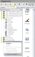
We make sure first that we have active the group of palettes where we want to add the new one. We also need to have the drawing containing the Blocks open. From the design center ("Ctrl + 2" or ADCENTER command) we select the file with the blocks we want to add, right click it and select "create palette". See the image for a visual aid to do this.
The result will be a palette with the anme of the file, and ALL the Blocks that the file contained, organized alphabetically.
Thanks to Aarti for this tip.
kick it on CadKicks.com

Show me more...

Photoshop: Zoom using the scroll wheel

Did you know that you can use the scroll wheel to zoom in and out in Photoshop?
Catala - Castellano
Changing from one software to another is sometimes annoying. There are certain things we give for granted that it is hard to get use to not have them in some software.
One of this things is the zooming feature using the Scroll Wheel. It is a very standard feature in most CAD programs. But it is not the default setting for Adobe software.
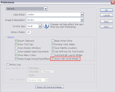
Luckily there is a work around. If we want to be able to use the scroll wheel to zoom in and out in Photoshop, we have two options. We can get used to press Alt (option in MAC) and then use the scroll wheel. This is the default setting in Photoshop. Or we can configure PS to zoom in and out automatically when we turn the scroll wheel.
To do that we simply need to go to Edit --> Preferences --> General. And check the box "Zoom with Scroll Wheel". Easy and simple, see the image below.

Show me more...

SketchUp: VRAY plugin works also on version 7

ASGVIS has announced that their VRAY plugin for SketchUp is ready to work on SketchUp 7 too.
Castellano - Català - Deutsch
ASGVIS released some time ago a plugin to be able to use VRAY render inside SketchUp. Recently they announced that the plugin itself is ready to be used in the recently released new version 7 of SketchUp.
The only tricky part is that you can not have the plugin running for both versions 6 and 7 at the same time. So, if you are just planning to try version 7 but keep version 6 maybe you want to hold on before switching Vray t thenew version.
I tried it with version 6 some time ago and I sincerely didnñt manage to get good results. But the gallery that ASGVIS has only proofs that it is proably just due tome not putting enough time into it.
You can download a free 30 day trial here and give it a shot. The license is nearly $800 so you better be sure it is what you want before investing that money, specially considering that competing NextLimit sells its software
Maxwell Render with far more functionality plus all availale Plugins for $995.

Show me more...

AutoCAD 2009: Disabling the annoying information pane

Turn off that white information pane that shows when you hover over an XREF, Block, etc
Català - Castellano
Sometimes new features are more an annoyance than a real benefit for the user. AutoCAD 2009 has some of these. One of them is that white box or pane with information that shows when you keep the cursor over an XREF, Block or almost any type of object.
AutoCAD 2009 has awesome new features and although this one might be useful in some way, I find it extremely annoying. Well finally someone told me how to disable it. It is simple.
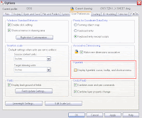
Go to Tools --> Options --> User Preferences. There, uncheck the box that says "Display hyperlink cursor, tooltip, and shortcut menu.
I haven't found any system variable for this (i think there is none so far) so it will have to be disabled by accessing the OPTIONS dialog box. Click on the image to get a view of the Tab and box you need to uncheck to disable this feature.
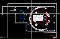
Update: There´s been a couple of comments saying this trick is wrong. It is not, everything I post here is verified by myself, I repeat, I only post stuff that I checked that works. I think the confusion of some folks is to what d0 I mean by "annoying white infomation pane" See the picture please on the right to understand what I meant.
kick it on CadKicks.com

Show me more...

AutoCAD Architecture: Hiding 2D objects (actually obscuring them)

Trying to find a way to hide single objects I came across a way to obscure them.
Català - Castellano
Someone told me today at work that Microstation has an option where you can hide objects regardless of their layer. I really don't know if that is true (haven't used Microstation for almost two years) but I was asked to find a similar command in AutoCAD. Be aware, I wasn´t successful.
But every failure has a part of learning, in the process, I discovered the AEC Tool: Obscure. You can access it by selecting geometry -- Right click -- AEC Tools -- Obscure. Or you can directly type the LINEWORKOBSCURE command.
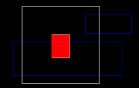
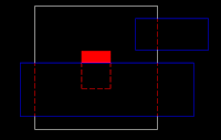
See the two pictures below to appreciate what this command does.
On the image above we want to hide the withe and red geometry behind te white geometry. The process is simple. We select the geometry we want to show as hidden (in this case the white and red rectangles), right click -- AEC Modify Tools -- Obscure. Then we will be asked to select the geometry that is going to create the obscuring boundary. We select the two blue rectangles. Done, see the result below.
See how all the "hidden" geometry becomes dotted lines, and how even the solid hatch filing the central rectangle is "hidden" behind the blue rectangle. I say "hidden" because there is nothing actually hidden here, what ACA does is break the original geomtrey using the boundaries we gave it, and change the geometry inside those boundaries to a layer with hidden line properties.
It ia a useful command, but don't forget that this is pure 2D. I am still tring to figure out a way to configure the properties of this hidden geometry layer. By default the layer is called Aec-Detail-Hidden, but I know that this can be modified (as wellas the layer properties) because in my company when using this command the hidden geometry comes in one of our standard hidden layers. Will investigate a bit more and post the solution if I find it. Or do you knowhow to do it?!?

Show me more...