AutoCAD tutorial: Creating a dynamic block 1.0

Learn step by step how to create a dynamic block.
Català - Castellano
Dynamic blocks are a very important resource to increase productivity. What would require several different blocks can be achieved with a single dynamic one if we know how to give the right editing properties to them.
In this first tutorial we will create a dynamic block for an escalator. The block will be able to be stretched to have different step widths, overall lengths (to cover different floor to floor heights) and some other cool properties.
First of all we have to create a standard block. I got the escalator DWG from Schindler, the block is good enough for the precise height you request it. This is the drawing we will start with.
We will name this block Dynamic Escalator. To make this block a dynamic block we have to add Parameters and Actions to the block. To do so, select the blog and type BE (Block Editor). Inside the Block Editor you will find a series of buttons that will allow you to do that.

We have to plan what we want to do, and probably you will have to do things twice or trice till you make the block work as you want. To start we will set the parameters and actions that will let us modify the step width of the escalator. This are the steps we will follow.
  • Click the parameter button
  • Select Linear as Parameter Type.
  • Select the two edges of one of the steps.
  • Choose to show only one grip.
This is how the parameter should look after we created it.

Now, we need to add an action to this parameter. This are the steps to follow.
  • Click the Action Button
  • Select the Parameter
  • Choose Stretch As the Action Type
  • Select the Grip
  • Select the stretch Polygon (like you would select the objects using the STRETCH command)
  • Select the objects to be stretched.
The block should resemble to this:
Try to save and go out of the block editor. Check that the block behaves the way it is expected. If it does we will continue adding parameters and actions.
Next we will make the block stretchable in length. This will require more than one action since we not only want to stretch the lines, but also make extra steps appear when we stretch the block.
We will do the following:
  • Add a linear parameter to the length of the block
  • Add a stretch action to stretch all the lateral lines of the escalator.
  • Add an Array action to make new steps when the block is edited.
The first think we will have to do is to erase all the step lines except one so we can use the array action properly. With that done, we add a linear parameter to the length of the block. See that I also added some markers on a non plot layer so I know certain points where the length of the escalator corresponds to certain floor to floor height (like 5m, 6m, 7m etc.). The block should look something like this at this point (inside the Block Editor Interface):


We want the step lines to show all the way from end to end of the escalator. We need to add an array action to the same linear parameter that we are using for stretching the block in length. We follow these process:
  • Click the action Button
  • Select the linear parameter.
  • Choose Array as the action
  • Select the single step line we have when prompted to select objects
It is important that the linear parameter starts on the step line and ends where the steps are supposed to disappear, otherwise you might get step lines out of the boundaries they are supposed to be. Again, save the block and go out of the block editor interface. Check that the parameters and actions added work as desired.
We still want to add a couple more parameters to the block. First we want text and an arrow that shows if the escalator is going down or arriving from the level below. We will use the text DN for going down, and AR for an escalator that arrives to the level we are showing. First we prepare the block for the actions we want to add.
  • We type both texts AR and DN on the same exact position.
  • We mirror the arrow head so we have a line with arrows on both sides.
It should look like the image above. What we want to do is to be able to use the same block either for an elevator going down (DN text with the arrow pointing away form the text) and an elevator arriving to the level we are showing (AR text with the arrow pointing to it). We will have to use a different parameter type called Visibility. It is important to know the buttons related to the visibility parameter. They are situated on the upper right corner of the block editor interface. They are the following.

  1. Toggles objects on other visibility states on and off.
  2. Makes an object visible in the current visibility state
  3. Hides an object form the current visibility state
  4. Calls the visibility states dialog box (where we will create different visibility states)
So the steps we will follow are:
  • first we have to do is click button #4 and create a new visibility state called AR, and rename the existing one as DN.
  • Having DN as active visibility state select the AR text and the arrowhead pointing to it and click button #3 to hide them. (the objects will diappear if you didn't click button #1, if you did the objects will be faded)
  • Turn AR visibility state active, select DN text and arrowhead pointing away from it and hide them (button #3)
Let's check if it worked. Save the block and get out of the BE interface. Select the block and click on the grip corresponding to the visibility parameter. You'll be able to select the visibility mode you want so with the same block you will be able to show both an escalator going down and another arriving to the level we are. See the too pictures below.

The last edit I added to the block is a rotation aprameter and action that allows me to rotate the text to any position I want. The idea is that no matter in which angle the escalator is placed, the text should always be facing the right way. See the image below to understand what I mean..
I am not going to detail the steps for this since it is pretty simple and similar to the rest of the process. Just think of using a rotation parameter and action applied to the center of the text.
If you want to check the escalator file, you can download it here.

Show me more...

SketchUp Plugins: Weld

A must have Plugin for SketchUp. Weld lines to hide edges and clean geometry.
Català - Castellano - Deutsch
One of my favorite plugins for SketchUp is the Weld plugin. What this plugin does is basically, as its name says, to weld lines together. This might read very basic, but it becomes very important in many situations. Let´s see some examples.
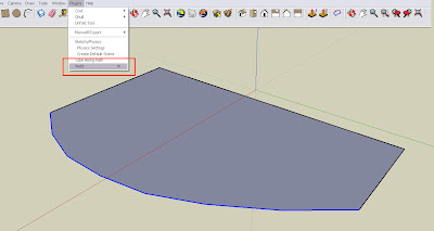
The basic use is to join lines together. So if we have a bunch of lines and we want to transform them into a sort of polyline, we can do that selecting the lines and going to Plugins - Weld. I personally have a shrtcut for Weld that is the letter W, since I use it very very often.
The plugin has also another use that is to create faces from a bunch of interconnected lines. Once we select to run the plugin, it will as as two questions.
- Close Curve?
- Find faces for this curve?
If we select yes in the first questions, SketchUp automatically draws a line to close the curve. A yes to the second one will create a face if possible.
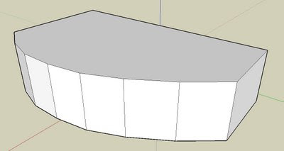
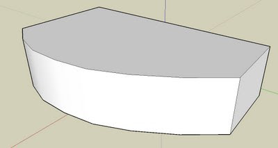
The third use is to hide edges for extruded objects. When we extrude a face, all the corners become edges. Something like this:But in this case we don't want to see the edges on the curved surface. We could select those edges and hide them, or better we can weld the lines that create that curved surface before we extrude the face:
By selecting the lines and welding them together we will get a new object with only 4 vertical edges, instead of having all those shown in the first image.
If you want to download the plugin click here.

Update: The same that I had done here with the weld plugin to extrude the curved face without seeing the intermediate edges, can be achieved without the weld plugin by using the Soften Edges Tool from SketchUp. Both process are equally quick, the results are almost the same.

Show me more...

AutoCAD 2009: New System Variables

A full list of the new system variables available for AutoCAD 2009.As mentioned on the previous post the guys of www.hyperpics.com have a great list of system variables for AutoCAD. Here I just want to list those new to AutoCAD 2009 for those whO start using the newest release and need a directory of what's new. With time I´ll try to describe the ones I find most relevant.
  • ACTPATH
  • ACTRECORDSTATE
  • ACTRECPATH
  • ACTUI
  • CAPTURETHUMBNAILS
  • DGNIMPORTMAX
  • DGNMAPPINGPATH
  • GEOLATLONGFORMAT
  • GEOMARKETVISIBILITY
  • LAYERMANAGERSTATE
  • MENUBAR
  • MLEADERSCALE
  • MTEXTTOOLBAR
  • NAVSWHEELMODE
  • NAVSWHEELOPACITYBIG
  • NAVSWHEELOPACITYMINI
  • NAVSWHEELSIZEBIG
  • NAVSWHEELSIZEMINI
  • NAVVCUBEDISPLAY
  • NAVVCUBELOCATION
  • NAVVCUBEOPACITY
  • NAVVCUBEORIENT
  • NAVVCUBESIZE
  • OPENPARTIAL
  • PREVIEWTYPE
  • PUBLISHHATCH
  • QPLOCATION
  • QPMODE
  • QVDRAWINGPIN
  • QVLAYOUTPIN
  • RIBBONSTATE
  • ROLLOVERTIPS
  • SHOWMOTIONPIN
  • STATUSBAR
  • THUMBSIZE

Show me more...

AutoCAD: List of system variables

We´v been commenting on many system variables. Discover them and get a link for the full list.
Català - Castellano
The list of system variables that AutoCAD has used or uses nowadays is too long to be included in a simple blog post (apparently 690 variables). Luckily the guys of www.hyperpics.com have a great list of the system variables available describing on which version are they available, released or suppressed.
This post just wants to acknowledge their effort putting together such a list and quickly list those that have been already analyzed by CAD Addict. Here is the list with links to those that have been previously described (future ones will be added to the end of the list).
All the posts describing system variables can be found through this link or using the search box on the side bar. For individual system variable descriptions click each one of the following:
  • ANNOAUTOSCALE: Control if annotative objects get new scales automatically.
  • EDGEMODE: Controls if the drawn objects work as cutting edges or their extension.
  • FILEDIA: Controls if Dialog Boxes are shown or not
  • FULLPLOTPATH: Send the full path to the plotter or just the file name
  • LAYLOCKFADECTL: Control the fading of locked layers
  • MAXSORT: Set the maximum number of objects in lists.
  • MENUBAR: Shows or hides the classic menu bar with pull down menus.
  • MIRRTEXT: Controls if mirrored text remain readable or truly flipped.
  • PELLIPSE: Controls if the ellipses are created as such or as polylines
  • PREVIEWFILTER: Set which objects have a selection preview
  • PROJMODE: control the projection mode for TRIM and EXTEND commands.
  • SELECTIONPREVIEW: Activate or deactivate the selection preview feature.
  • TASKBAR: Shows multiple windows or a single one on the windows taskbar.
  • VISRETAIN: Control the retention of visual changes on XREFs.
  • XCLIPFRAME: Shows or hides the frame used to clip XREFs, Blocks, etc
  • XDWGFADECTL: Controls the fading of inserted XREFs
  • XFADECTL: Control fading ob objects not on active space.

On the next post I am going to be listing the System variables that are new to AutoCAD 2009.

Show me more...

Photoshop: Fade Layers

A quick trick to create a fading effect on photoshop layers.
Català - Castellano
This is a bit off topic, but since Photoshop is one of the main tools we use to present what we first draw or model i think it is not completely out of place.
The fading effect for a layer is a very successful effect when making presentations. We might want to fade an image that we have to blend into another one or simply to make it disappear gradually.
The process is very simple. I´ll use a picture I took last week in Toronto.
I want the picture to fade till disappear. We need to add a layer mask. What we need to do is to select the layer we want to fade and click on the button shown in the image below.This will add a layer mask to the layer we want to fade. A layer mask is basically a transparency map for the layer it is applied to. Once we create the layer mask we will see this:
The layer mask is completely white by default, which means that all the image is set to opaque. If we want to fade the image we must add a gradient from white to black to achieve the fading effect we are looking for. Be sure that you have the layer mas selected and not the layer itself.
In this case I add a circular gradient to make the image fade equally from a center point to the edges. This is the gradient applied to the layer mask:And this is the result

Show me more...

AutoCAD: Fading Of Locked Layers

It is easy to control the fading of the locked layers if you know the right system variables.There are two system variables that will let us control the fading intensity of locked layers.
LAYLOCKFADECTL directly controls the intensity of the fading of locked layers. The higher the value we enter the more the layers will fade to show that they are locked.
XFADECTL controls the fading when we enter the REFEDIT mode. Everything that is not being edited will fade according to the intensity we set on this system variable.

Show me more...

AutoCAD: Taking advantatge of the Grips.

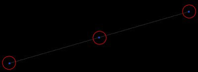
Do you take full advantage of the grips? They are more useful than you think.So what are the grips? For those newbies, the grips are those dots you see at the endpoint and midpoint of a line when you select it.So what are the grips? For those newbies, the grips are those dots you see at the endpoint and midpoint of a line when you select it.


At a first glance they might seem like a worthless feature, but they can actually save us a good amount of time if we know how to use them to the full extent. The basic use that almost everyone knows is to use the grips to stretch objects. If we select a line and click on one of the endpoint grips, we will be able to stretch the line from that point. It is actually kind of an automatized "Express Tool". When you click on the grip, check the command line bar, and you will see that the command STRETCH has been entered automatically.
If instead of the endpoint grip we select the midpoint grip, we will be able to move the line instead of modifying it. (see that the command that appears is still stretch, although in this case we move the line, we don't stretch it).
Well this were the basics that anyone knows, here comes the interesting part. Try to do the two previous steps while pressing Ctrl (you actually must have Ctrl pressed when you click the new position of the grip) What does it do? well it stretches or moves the line as well, but this time making a copy of the original that remains untouched. SO you could create all the lines you see below based on the original line without typing any command. Simpli hold Ctrl while clicking the new position of the grip (you only need to hold Ctrl for the first line, the subsequent ones will be copies without pressing Ctrl)


Is that it?? Not yet. What other keys can we use? Let's try Shift. As in many programs shift may be used to select multiple objects, or in today's scope, multiple grips. If we hold Shift while selecting a grip this will turn red, but it won't be dragged with the mouse pointer. If we keep selecting grips while pressing Shift, the grips will be added to the selection and then we can do with them more or less the same that we did to a single grip. For a single line this might not be very useful, but it is when we have a polyline or if we want to select grips of multiple objects. On the picture below we selected all the grips of the upper part of four rectangles. The we can stretch them all together.

I know...We culd have simple selected those edges and use the Stretch command, but think of a drawing with complex geometry intersecting this rectangles that would make it hard to only select the edges we want to stretch.
And last but not least, we will try one more key. ENTER. Surprise! If we select a grip, we already said the the STRETCH command becomes active. But if we press ENTER after we have the grip selected, the command active will jump from STRETCH to MOVE, ROTATE, SCALE and MIRROR. ROTATE, SCALE and MIRROR will use the selected grip (or the last clicked before hiting ENTER) as a base point.
All these little tricks will save you a lot of time if you have them in mind. For those using AutoCAD Architecture see also this post for how to use the Grips of AECPolygons.

Show me more...

SketchUp: Teach it to your kids

A set of books to introduce SketchUp to the little ones.If you want your kids to become architects in the future or simply want them to do something more useful than playing shot'em'up games, maybe you should consider buying this set of books.
Author Bonnie Roskes has published a series of books to learn SketchUp, but they have the peculiarity of being intended for kids.
The series start with ModelMetricks Basics Series, a series of 4 books for the beginner kid. These are the 4 books of this first series:
1.- Home, Sweet Home, on this first book kids (age 8 to 15) can learn how to model different types of houses and color them. (Mac version of the Book here)
2.- Strange Buildings, probably the best of the whole series, kids can design, factories, towers, curved buildings in a very funny way.(Mac version of the Book here)
3.- Kids as Architects, on the third book kids take the role of the architect to design really surprisingly shaped buildings. (Mac version of the Book here)
4.- Go to your Room, the fourth book will allow children to design their own bedroom.( Mac version of the book here)

There is an intermediate and advanced series of the books as well, so if your kids love this first series you know what's the next present!

Show me more...

AutoCAD: Excessive Xref Scales

How to get rid of the long and annoying list of Xref scales.
Català - Castellano
One thing we noticed at work after installing AutoCAD Architecture 2008 was the extremely long list of scales when a file had Xrefs. We would get some scales like "1:20_XREF_XREF_XREF_XREF_XREF_XREF".
The manual procedure to get rid of them is to use the command SCALELISTEDIT, and remove all the scales that we didn´t want to see or use. This can be a pretty tedious process if it needs to be done on lot of files.
A way around is to create a script containing this line (COMMAND "-SCALELISTEDIT""R""Y""E") and batch run it in all the files we need. We will need a program like ScriptPro that will allow us to batch run the script in as many files as we want.
Good news for those who are planning to update to AutoCAD 2009, the issue has been partially solved by adding an option on the scale list. We can select to "hide Xref Scales", so we don't have to deal or see the long list of scales that are mostly useless for the most of us.

Show me more...

AutoCAD: Customizing the Break Command

The break command has an annoying behaivour. But there is a way to fix that.I find the break command default behavior a bit annoying. The click we do to select a line becomes the first breaking point which give us no accuracy on where we are selecting.
There are two ways around this.
First option is to modify the macro for the button "Break" in the modify tool bar (note that if your CAD manager has disabled your rights to modify the tool bars you will have to create a custom tool bar where we you will add a button for the Break Command). Then we modify the macro associated to the button from ^C^C_break to ^C^C_break \f so AutoCAD will automatically prompt us for the first Break point after selecting the object we want to break.
The other way around is much simpler, and it is basically to remember that if we press "Shift+RightClick" we will get the temporary Osnap contextual menu. So when break command prompt us to select the object we Shift+Right Click and select the Osnap that fits to our needs. This second option though give us less flexibility on the point we can select since we are tied to the Onap we choose from the contextual right click menu.
I am still trying to find out how to incorporate the ^C^C_break \f macro into a command I can enter without using toolbars (I am a keyboard shortcut freak, I love a clean screen with no toolbars) but I guess I need some AutoLisp I donñt have time right now to figure out...So any imput from you guys is welcome.

Show me more...

Maxwell Render: Grouping Emitters

Solving some issues with SketchUp exporting and emitters for Maxwell.In old versions of Maxwell Render, all Objects with the same material would be treated as one in Maxwell Studio. In the last version I tried, 1.6x that changed. Geometry is respected and that means that objects don´t get grouped together just by having the same material.
See that my system lately is to model in SketchUp and export to Maxwell to render there. Previously I used to set different emitters for those elements I wanted to control separately with the Multilight feature. That made it very simple to control lighting. If for instance we had 50 street lamps and we set an emitter material in them, we would control the intensity of that material with a simple control slider in Maxwell Render.
What changed in the last version (and I assume that will go on on the recently released version 1.7)
is that if we have 50 objects with the same emitter each object will have a different control slider in the Emixer in Maxwell Studio. Although I understand that more flexibility is always a good thing, it might be pretty annoying to have 50 sliders to control 50 emitters that you probably want to produce the same light intensity.
The solution I found is pretty simple, what I do is I group all the emitters (or all the objects containing emitters) that I want to control with one single button into a Component in SketchUp. That way when controlling the lighting in the Emixer in Maxwell Render, all those objects will be set by one single slider.

Show me more...

AutoCAD Architecure: Forget about Associative Hatch Patterns

For a long time I struggled to remember to check the box "Associative" when creating Hatch Patterns. Now I know I don't need to do this anymore.

For a long time I struggled to remember to check the box "Associative" when creating hatch patterns. Without that Box checked it was really hard to modify any existing hatch pattern. But even creating an associative pattern didn't make it very flexible to work with them. A lot of times the boundary bothers us so we end up erasing it and doing that we loose the associativity of the pattern.
AutoCAD Architecture has some features that make hatch associativity something from the past. When we have a Hatch Pattern, we can select it and right click on it. We will get the contextual menu shown on the left side of this post.
The beauty of it is that if we click on generate boundary, an AEC polygon will be generated. We can then modify that polygon to fit our new hatch needs and after that we simply select the Hatch - Right Click - Set Boundary - And we will select the modified polygon. We will we prompt to decide if we want to erase the polygon or not, which I personally recommend say yes, since it is so easy to recreate them.
But this is not all, AutoCAD Architecture has another set of tools that will improve our work flow, the AEC Modify Tools. These tools will allow us to easily modify our hatch by Merging it with other entities, Subtracting parts of it or dividing it in two. I will write a post soon with more details about the AEC Modify Tools.
For those Using classic AutoCAD classic these features are not available. You can Recreate the Boundary of a Hatch by double clicking it and selecting "Recreate Boundary". I don´t think there is anything similar to the AEC Modify tools in the classic version of AutoCAD.
If you are in the AEC industry I seriously encourage you to jump ASAP to AutoCAD Architecture whenever you need to update your CAD software. It boosts the work flow of your employees many times. To learn all the features specific to AutoCAD Architecture you might want to buy this book.

Show me more...