Architecture Software Acronyms

What do all these acronyms stand for? CAD, CAM, BIM, IPD, CAE, AEC...Not so long ago, a friend of mine started publishing in his blog a list of Acronyms related to the Business Intelligence field. For a long time I wanted to do something similar, so finally that pushed my laziness away and here comes the list.
Since this website deals with Architecture related software, I'll try to list all those acronyms related to this topic, or at list the ones that I am acquainted with. The list might get updated as new abbreviations develop or I get to know them. Here is the list:
  • CAD: Computer Aided Design. Sometimes also referred as CADD (for Computer aided Design and Drafting). The most basic one (and the one that gives name to this website). Although originally understood for 2D drafting with a computer, nowadays is also used to refer to 3d Design. Most of the big names in CAD software deliver products with strong 3D modelling capabilities. The Almighty AutoCAD is the industry most widely spread CAD package in the construction industry.
  • CAM: Computer Aided Manufacturing. Originally Computer Aided Machining. Is the use of computers (and designs generally prooduced with CAD systems), to streamline the production of goods.
  • CAE: Computer Aided Engineering. Although in many countries the functions of CAE software are performed by Engineers and not by Architects, in some places like Spain, the Architect still plays the main role in this field, specially on Building Structural Analysis. The tasks accomplished with this software are analysis, simulation, design, diagnosis of built solutions (and thus, of buildings) and many others. The software range might go from CAD/CAM software to Structural analysis programs, Heating and AC system calculators, etc.
  • AEC: Architecture Engineering and Construction. The explanation is kind of obvious, software or any tool related to these 3 fields. The abbreviation is used by many BIM software to name some of the tools such as the AEC Polygons.
  • BIM: Building Information Modelling. This is were the industry seems to be strongly moving to. BIM means not only building a 3D modell of a building, but also adding to these model all sorts of real life properties, such as materials, plumbing, structure, etc. It is in certain way like building in a computer a complete model previous to the construction of the real thing. ArchiCAD is known to be the first BIM software (released in 1987), other big names on BIM are Revit by Autodesk, Allplan by Nemetschek or Bentley Architecture (the BIM version of Microstation).
  • IPD: Integrated Project Delivery. Not very extensively explained, seems to be a step forward from BIM. A way to not only build a model that has all the information of a project, but also to create an interconnection between Architects, Owners and Constructors (and all providers involved in the process) to minimize costs and maximize building efficiency. In this video, you can see a brief (and a bit stressing) introduction to IPD.
  • CGI: Computer Generated Imagery. A wide meaning of this would be any image you produced using the computer (kinda obvious eh!). The use of the term refers mostly to 3D imagery and animations produced using any of the softwares explained above (and many others)
There are other 3 letter Acronyms related to architecture like GMP (Guaranteed Maximum Price) and others, but I am not going to explain them here since they have few to do with Architecture related Software

Show me more...

AutoCAD: PROJMODE system variable

Control the projection mode for TRIM and EXTEND commands. Recently a colleague asked me: "When I am unable to trim lines, because “EDGE IS PERPENDICULAR TO UCS XY PLANE”.. what do I do?". I sincerely had no idea, but since "I don't know" is not the kind of answer I like to give I started looking for an answer. Googleling the problem showed that the quick solution was to set PROJMODE to 0. Tried and it worked. The next step was to know what was PROJMODE.
PROJMODE is a system variable that allows us to control the projection settings for the TRIM and EXTEND Commands. The default option for PROJMODE is 1. These are the three states of the variable and their result:
  • PROJMODE (0): True 3D mode. This means that if two objects are not coplanar, you will not be able to TRIM or EXTEND using them as a reference.
  • PROJMODE (1): Default setting. It projects to the XY plane of the current UCS. See that this will allow you to trim or extend lines that have different Z values, but the lines will remain on different planes. Remember that the command FLATTEN is an Express Tool that allows you to bring all geometry to Z=0
  • PROJMODE (2): It projects to the XY plane of the current view. If your view is alligned with the current UCS (using the PLAN command or alligning the view by default to the UCS) there is no difference between setting the variable to 1 or to 2. If the view has been rotated the results on trimming will vary.
I still have not very clearly found out the reasons for initial error message, but at least we found a work around and we learned something new.

Show me more...

SketchUp: Turning the Rotate Plane 90 degrees

How can you turn the rotate plane to be 90 degrees of a face? I've been struggling for so long and it was so easy...
Català - Castellano
For a long time I struggled to figure out how to rotate a surface on any plane that wasn't that of the surface itself.
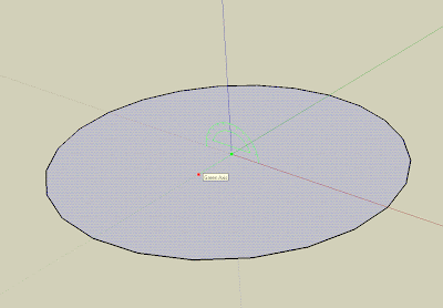
Let me say it differently, imagine that you draw a circle, and then you want to turn that circle 90 degrees.The rotate tool will magnet to the
circle plane(the plane perpendicular to the blue axis if you drew the circle on the ground). Rotating the circle using the green or red planes becomes troublesome without this.
And THIS is basically to know that if you click and drag on the surface of that circle, you'll be able to select any perpendicular plane to the surface.
This tip is, funny enough, kind of explained in the introductory tips of sketchup, under the chapter "creating a sphere". I think it is a good lesson for me to never underestimate wha
t you can find in the default help of a program...
Show me more...

SketchUp: Bonus Packs, Extra Materials and Components

Did you know that Google itself provides more Components and Materials than those installed in SketchUp?
Deutsch - Català - Castellano
The installation of SketchUp will provide you with a reasonable amount of components and materials. But if you feel like you need more, be aware that Google itself provides free bonus packs to download from this website.
Specially useful is (was) the set of new materials. (update: the set of extra materials is no longer available online) Be aware that installing this bonus packs will overwrite the previous components if they are of the same type. But don't worry, these extras come with all the standard components and materials that you normally find in SketchUp.

Show me more...

SketchUp: Export Multiple Scene Images at Once

Exporting multiple Scene Images might be tedious without this trick.
Català - Castellano
From pushpullbar and a post by Torlai we find a solution to a common problem when working with a large number of scenes. What if I want to export easily a JPEG of each scene at once?
The 4 easy steps to follow are very simple:
  1. Go to Window -> Model Info -> Animation -> uncheck the Scence Transitions box.
  2. Go to the File menu -> Export -> Animation, set the file type to JPEG
  3. Use the Options button to adjust the size of the images.
  4. Export animation.

Show me more...

SketchUp: Hide All the Edges.

There is an easy way to hide all the edges of an object in SketchUp.I was recently working on a complex SketchUp file, and for the sake of the presentation I needed to hide all the edges of some very complex objects. I wondered why there is no option like Hide --> All edges. So we would keep the faces visible but the edges hidden.
The trick is simple. Remember that SketchUp has many different modes to show faces and edges. One of these modes is the wireframe mode. This will be or work around this problem.
We will edit the component or group that we want to have with hidden edges and we turn on the wireframe mode on. Then we will see only the edges, so we select all the geometry and go to Edit --> Hide. That simple, after that all the edges will be hidden. Switch on any mode that shows the faces and you will find your geometry with hidden edges.

Show me more...

SketchUp Plugins: Volume Calculator

Discover a plugin that will allow you to calculate volumes of objects.
Català - Castellano - Deutsch
There is a useful plugin for Sketchup called VolumeCalculator21.rb. It allows us to calculate the volume of an object. The only requirements are that it needs the object to be a group or component, and for maximum accuracy the geometry has to be clean. For clean geometry basically we need that each edge has two faces, no more no less, but that will ensure that the volume calculation is precise.
I tried it with basic geometry and the results were exact, when I tried it with very complex and not clean geometry, I got different results from time to time, so the importance of using clean geometry is very clear.
Still, I think it is a plugin worth having. To use it (after downloading the plugin and saving it to the plugins folder in SketchUp) select the group or component you want to know its volume, right click, and you will find an option called volume. Select that and you will get a dialog box that will ask you for which units you want to use and other options. It is very simple to use.
You can download the plugin here. Thanks to the author TGI.

Show me more...

AutoCAD: Meet the OSNAPs

Have you ever wondered what does each and every Osnap do? I did, and I tried to find out.
Castellano - Català
On my personal experience and according to what colleagues and friends tell me, it seems that none of us takes full advantage of all the OSNAPs available in AutoCAD. I
think the way we work is mostly based on the way we always did, so we tent to not try new things, we like routine.
Once said that, I must admit that many times discovering a good way to use some of the OSNAPS makes your work flow improve considerably. So it is worth trying all of them and seeing what can they do to improve your AutoCAD proficiency. As a way of self discovering some of the OSNAPs I never use, and to share those that I think are the most useful, here is a compiled list of them with some quick description of what are they for and how they improve your drafting experience.
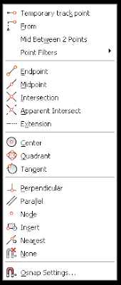
First a quick tip for those who don't know this. If you press Shift+Right Click on the drawing space, a contextual menu with the list of OSNAPs will appear ( See this previous post for more information about this). We will use this contextual menu (the picture on the left) as a list to describe each Osnap individually. The letters between parenthesis are the text entry/shortcut for those Osnaps
  • Temporary Track Point (tt): If for any reason you like to work with Object Snap Tracking (OST) not active, this OSNAP will allow you to track from one point you select. It has a weird behaviour I have to say, because it seems not possible to use it twice in a row (I need to investigate more because so far it doesn't make sense)
  • From (from): It allows you to click on a point and set the distance from that point you want to start or finish drawing. Almost impossible to use accurately if OST is Off, unless you use relative co-ordinates. It is actually useless in most situations because OST already allows you to do most of what "from" does (if someone knows any other use of this please don't hesitate to collaborate)
  • Mid Between two points - (m2p): My favourite one, it allows you to snap on a point exactly in the middle of two given points. Very very useful and quite unknown since it doesn't appear in the Osnap Settings Dialog Box.
  • Point Filters (.x .y .z): For those who used Microstation and miss that pressing the space bar to lock one of the Axis, this will make the trick. We can, for instance select to lock X, select the X coordinate that we want locked, and then choose any point. The resultant point will have the X we locked using this Osnap and the X and Z of the last selection. It can combine multiple axis locked, XY, XZ, YZ.
  • Endpoint ( end ): One of the most basic ones. Not much is needed to mention since normally everyone works with this one permanently active. It will snap to one of the endpoints of an object, showing a square sign.
  • Midpoint (mid): Another of the classics, it snaps to the midpoint of an object, it shows the triangle sign.
  • Intersection (int): It snaps to the intersection of two objects. The objects need to have a real intersection, if no intersection is found between two objects that apparently are intersecting, check the Z values of this objects, since one or both might be not on Z=0. The sign is the X
  • Apparent Intersection (app): What the previous osnap doesn't find as an intersection this one will. According to the active view it will ind the visual intersection between two objects. The sign is a square with an X inside.
  • Extension (ext): It will let you choose any point on the extension of an arc or line.
  • Centre (cen): Points to the center of an arc, circle or ellipse. The marker is a circle.
  • Quadrant (qua): Points to 4 Points on a Circle or Ellipse. These 4 points depend on how was the UCS when this geometry was drawn and will always follow the direction of this original UCS. They would be the North South West and East coordinates of an Arc or Ellipse, being North where the Y axis is pointing. In Arcs or Portions of Ellipse they behave as if the Circle or Ellipse was complete, but only those that fall on the arc or portion o ellipse will be selectable. The sign is a square tilted 45 degrees.
  • Tangent (tan): Allows to draw lines tangent to circles, arcs or ellipses. It doesn't work if we are drawing an arc. The sign is a circle with a line.
  • Perpendicular (per): Finds the point that makes the line you are drawing perpendicular to the geometry you want. It can be used with lines, arcs, circles and ellipses. The sign is like an inverted T.
  • Parallel (par): Only for lines. It allows you to draw a line parallel to another one. It is less intuitive to find out how to use it. You must select the first point, then chose Parallel Osnap if it's not permanently active, point on the line you want the new one to be parallel to. A Double line sign appears, then move the cursor away to where the parallel line should be. A dotted line appears and the parallel Osnap marker shows on the original line, click a second point.
  • Node (nod): To snap on points or nodes. If you draw points using the POINT command, the only way to Snap o them is using "node" osnap. Also, when you use MEASURE or DIVIDE, points (nodes) will appear on the object (unless you use the [Block] option). The sign is a circle with an X.
  • Insert (ins): With this object snap you can point to the insertion points of objects like Blocks or Text. The sign is a shape consisting of two squares.
  • Nearest (Nea): Not to be used if you are trying to be precise, this osnap will select the closes point on an object, it can be useful for quick drawings and measurements, but it shouldn't be used for drawings requiring precision.
  • None (non): If at some point we need to select a point and we don't want to use any osnap we can select the None Osnap that will turn them all off for one click. It would be the equivalent of pressing F3.

Show me more...

Photoshop: ICON Creation Plugin.

Customize your desktop icons by easy creating your own .ico filesI always feel writing a bit off topic when adding Photoshop topics here, but still I think they are worth it since in some way or another, most of us end up being involved working with Photoshop at some point. This Plugin might be even more off Topic than others. Still, I felt to share it here.
Some of us like to personalize our desktop and folders in a visual way that help us find the Icons quickly. I personally hate having a whole bunch of Icons that basically have only the image of a folder. I like to differentiate each important folder with a personalized icon, so when i need to access them either from my desktop or from the Quick Access bar it is easy and very visual.
Long time ago I tried a program call Microangelo, that worked pretty good, but it has only a 30 day free trial.
Since Photoshop is probably already installed in your machine, a much better option is a plugin for this program that allows you to save any image to an ICON (.ico) format. On this website you can download the ICON plugin for free. The plugin is under the GNU General Public License.

Show me more...

AutoCAD: Showing the XClip Frame

Sometimes is important to find out the frame that was used to clip an XREF. There is a system variable for that.If you want to know the frame you or someone else has used to Clip a Block or an Xref, there is a system variable that alllows you to do so.
The System variable XCLIPFRAME toggles between visible and invisible XClip boundaries. Being 0 for invisible and 1 for visible. Some important points to consider are:
  • the Xclipframe will show on the same layer as the XREF or Block is.
  • Xclip frames inside Xrefs will appear in the drawing regardless of those Xrefs having other Xrefs as overlays or Attachments. And there seems to be no way to modify that.
Personally is not a system variable that I use very often, usually only to check what was the intention when creating certaing clipping on Xrefs.

kick it on CadKicks.com

Show me more...

AutoCAD without Windows?

Is there a way to use AutoCAD if you don't want to use Windows?Have you ever thought of moving away from Microsoft completely? Yeah right! You are an Architect depending on the all-mighty AutoCad... well most of us are, and there isn´t apparently a version of AutoCAD for GNU/Linux, or MAC.
Macs with Intel based processors can run the Bootcamp software which enables Windows to run in your computer, or Parallels Desktop which allows you to switch from MAC OS to Windows without rebooting your computer. Does that solves the problem for MAC users? Not really, if the only thing you want is to run AutoCAD then you are fine, but you still depend on running a copy of Windows XP or vista to be able to use AutoCAD.
Autodesk doesn't seem to be willing to go back to a multiplatform release for AutoCAD so there is not much you can do apparently. Nevertheless, a small firm in South Africa has proven itself successful in migrating away from Microsoft software (after some threads from Microsoft itself) and is running AutoCAD r14 under Debian GNU/Linux.
Good for them, I personally find it very hard to go back to older versions of AutoCAD, because to be honest, each new version is lately adding some extra useful tools that make themselves pretty indispensable once you get used to them.
So as I see it right now the only option is to go to one of the clones of AutoCAD that can run under Linux. About them not enough information and reviews have been released. Here is a list of some of the CAD clones released or in planning stage. And here another one of Free CAD software.
I personally donñt think it is time yet to move away from Windows if you are a professional CAD user. AutoCAD and AutoCAD architecture seem to be still light years away from the clones, and without any proven success on running AutoCAD 2007 or older on a Linux system, I'd rather stay away from that.

Show me more...

AutoCAD tutorial: Creating a dynamic block 1.0

Learn step by step how to create a dynamic block.
Català - Castellano
Dynamic blocks are a very important resource to increase productivity. What would require several different blocks can be achieved with a single dynamic one if we know how to give the right editing properties to them.
In this first tutorial we will create a dynamic block for an escalator. The block will be able to be stretched to have different step widths, overall lengths (to cover different floor to floor heights) and some other cool properties.
First of all we have to create a standard block. I got the escalator DWG from Schindler, the block is good enough for the precise height you request it. This is the drawing we will start with.
We will name this block Dynamic Escalator. To make this block a dynamic block we have to add Parameters and Actions to the block. To do so, select the blog and type BE (Block Editor). Inside the Block Editor you will find a series of buttons that will allow you to do that.

We have to plan what we want to do, and probably you will have to do things twice or trice till you make the block work as you want. To start we will set the parameters and actions that will let us modify the step width of the escalator. This are the steps we will follow.
  • Click the parameter button
  • Select Linear as Parameter Type.
  • Select the two edges of one of the steps.
  • Choose to show only one grip.
This is how the parameter should look after we created it.

Now, we need to add an action to this parameter. This are the steps to follow.
  • Click the Action Button
  • Select the Parameter
  • Choose Stretch As the Action Type
  • Select the Grip
  • Select the stretch Polygon (like you would select the objects using the STRETCH command)
  • Select the objects to be stretched.
The block should resemble to this:
Try to save and go out of the block editor. Check that the block behaves the way it is expected. If it does we will continue adding parameters and actions.
Next we will make the block stretchable in length. This will require more than one action since we not only want to stretch the lines, but also make extra steps appear when we stretch the block.
We will do the following:
  • Add a linear parameter to the length of the block
  • Add a stretch action to stretch all the lateral lines of the escalator.
  • Add an Array action to make new steps when the block is edited.
The first think we will have to do is to erase all the step lines except one so we can use the array action properly. With that done, we add a linear parameter to the length of the block. See that I also added some markers on a non plot layer so I know certain points where the length of the escalator corresponds to certain floor to floor height (like 5m, 6m, 7m etc.). The block should look something like this at this point (inside the Block Editor Interface):


We want the step lines to show all the way from end to end of the escalator. We need to add an array action to the same linear parameter that we are using for stretching the block in length. We follow these process:
  • Click the action Button
  • Select the linear parameter.
  • Choose Array as the action
  • Select the single step line we have when prompted to select objects
It is important that the linear parameter starts on the step line and ends where the steps are supposed to disappear, otherwise you might get step lines out of the boundaries they are supposed to be. Again, save the block and go out of the block editor interface. Check that the parameters and actions added work as desired.
We still want to add a couple more parameters to the block. First we want text and an arrow that shows if the escalator is going down or arriving from the level below. We will use the text DN for going down, and AR for an escalator that arrives to the level we are showing. First we prepare the block for the actions we want to add.
  • We type both texts AR and DN on the same exact position.
  • We mirror the arrow head so we have a line with arrows on both sides.
It should look like the image above. What we want to do is to be able to use the same block either for an elevator going down (DN text with the arrow pointing away form the text) and an elevator arriving to the level we are showing (AR text with the arrow pointing to it). We will have to use a different parameter type called Visibility. It is important to know the buttons related to the visibility parameter. They are situated on the upper right corner of the block editor interface. They are the following.

  1. Toggles objects on other visibility states on and off.
  2. Makes an object visible in the current visibility state
  3. Hides an object form the current visibility state
  4. Calls the visibility states dialog box (where we will create different visibility states)
So the steps we will follow are:
  • first we have to do is click button #4 and create a new visibility state called AR, and rename the existing one as DN.
  • Having DN as active visibility state select the AR text and the arrowhead pointing to it and click button #3 to hide them. (the objects will diappear if you didn't click button #1, if you did the objects will be faded)
  • Turn AR visibility state active, select DN text and arrowhead pointing away from it and hide them (button #3)
Let's check if it worked. Save the block and get out of the BE interface. Select the block and click on the grip corresponding to the visibility parameter. You'll be able to select the visibility mode you want so with the same block you will be able to show both an escalator going down and another arriving to the level we are. See the too pictures below.

The last edit I added to the block is a rotation aprameter and action that allows me to rotate the text to any position I want. The idea is that no matter in which angle the escalator is placed, the text should always be facing the right way. See the image below to understand what I mean..
I am not going to detail the steps for this since it is pretty simple and similar to the rest of the process. Just think of using a rotation parameter and action applied to the center of the text.
If you want to check the escalator file, you can download it here.

Show me more...