AutoCAD Architecture: Working with AEC Polygons

Forget about Polylines, AutoCAD Architecture has a much better entity.Forget about Polylines, AutoCAD Architecture has a much better entity than polylines, the AEC polygon (type "AECpolygon").
Once you draw one and select it you will realize that in opose of polylines that only have grips on their vertexes, the AEC polygons, have grips both in vertexes and middlepoint of each edge.


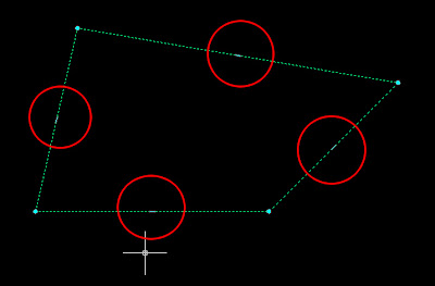
This is the first feature that makes them much better to work with than simple polylines. If we click those grips, we will be able to move that edge parallel to its original position, extending th adjacent edge to fit with the new position. See the picture.
But this is not the only thing we will be able to do. Click Ctrl and instead of ofsetting the edge you will be adding a new vertex.
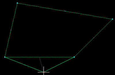
Click Ctrl again and you wil transform that edge into an arc.


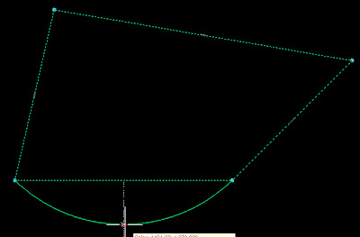
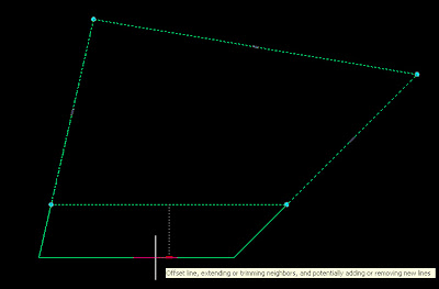
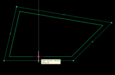
And for a last useful trick, press Ctrl again and you will get to offset all the edgs at a time.


Similar great features will happen if you click contr after selecting one of the vertex grips instead of the egde ones.

- Click the grip to move the vertex

- Press Ctrl once to remove the vertex

- Press Ctrl twice to Offset both edegs that intersect on that vertex.

As a last cool feature of the AEC polygons try to select the middle grip og an AEC polygon with an arc segment. You will also have several options:

- Click the grip to offset the arc segment (it might add some segments to the AEC polygon)

- Press Control Once and you´ll be able to modify the radius of the arc segment

- Press Ctrl again and you will straighten the segment

- Press Ctrl Again and you will add a vertex (and two arc segments)

- Press Ctrl again and you will offset all the faces of the AEC polygon.

I would say that, combined with the AEC modify tools, there is no reason to keep using the polylines.


Show me more...

AutoCAD: Disabling selection preview for Hatches

Do you get stuck in the selection preview of complex objects?A nice feature like the selection preview can become really annoying if we are working with dense hatch patterns.
What selection preview does is that it highlights the object we are going to select if we click the left mouse button. This works very nice and smooth with simple objects like lines, polylines, arcs, etc. It happens though that when we have a dense hatch, specially if it is a hatch made of dots it might take several seconds to show the selection preview due to the amount of objects in the hatch pattern.
Although we can turn off the selection preview turning the SELECTIONPREVIEW system variable to 0, what we actually want to do is to keep it on for some elements and off for some others like hatch patterns.
We have two options to do that.
  1. Set the system variable PREVIEWFILTER to 16, this will only exclude hatch patterns from the selection previews.
  2. Go to Format --> Options --> Selection Tab -->Visual Effects Options --> Advanced Options --> Uncheck the Box in front of Hatch Patterns.
See it in a couple of images for more detailed reference.


Show me more...

AutoCAD: Creating New Palette Group

Organize your blocks on a custom made tool palette.. We might want to create a new Tool Palette Group, let´s say to store all our blocks. The default groups in AutoCAD Architecture 2008 are Design, Document, Detailing and Visualization.
Lets assume that we want to create a new palette group for all the blocks we have.We have to right click on the lower corner of the tool palettes bar and select "Customize Palettes". We will get the following screen.
On the righ portion of the window we right click on a blank portion of the screen and we select "New group". We will name the new group "Blocks". Now to be able to see the new group it needs to have at least one palette. We can drag one palette from one of the default groups to our custom created one.
We click close and right click again the bottom corner of the tool palettes bar. A new line with the name of our group will appear.
Once in the new group we can add as many palettes as we want to it, and drag and drop the blocks to them so they can be easily accessed from any file.
Once we have created our grup and configured our palettes we might want to transfer them to other computers. See this post to know how to do that.


Show me more...

AutoCAD: Transferring Tool Palettes

Transfer your tool palettes from one computer to another.
Català - Castellano
After creating tool palettes in any of the AutoCAD versions, you might want to transfer them to other computers in your network. There is no Export command so finding the way to do so it might be a bit complicated.
Here is a link to the support site from autodesk about the topic. Basically it explains the following steps to do that. You have to use the content browser. But the explanation from autodesk I think is a bit short and might not be enough fo a newby. So here comes a kind of extended version of it.
To store the palettes you have created do the following:
  • Click on the content browser icon or type CONTENTBROWSER in the command line window.
  • Right click and "Add Catalog" --> Create New Catalog
  • Browse to a network location that all computers can access.
  • Save the catalog there.
  • Double click the new catalog that you have created.
  • Drag and drop the new palettes to from you palettes side bar to the Catalog.
In any computer where you want to add those palettes, follow these steps
  • CONTENTBROWSER
  • Add catalog --> Add an existing Catalog
  • Browse t the network location you specified before
  • Double click the new added catalog
  • Drag and drop the palettes you want from the catalog to your tool palettes bar. (see that it is not a simple drag and drop operation, you have to click in the palette you want to load in the contend browser and keep pressing the mouse button till a syringe icon loads, then drag to the tool palettes bar in AutoCAD
Note: After the initial transfer operation, you can add new tool palettes that you created by drag and dropping them to the Catalog in Content Browser. That will make any palette you created in one computer available to the other users on your network.
kick it on CadKicks.com

Show me more...

AutoCAD System Variable: VISRETAIN

Control if you want your XREFs to retain the visual changes or not.
Català - Castellano
Sometimes we change colors of the layers of an XREF for different reasons. Eventually we might want to get the layers to they original state. If we inserted the XRef on 0,0,0 coordinates and didn´t move it, scale it or clip it, we can just detach it and attach it again.
But in many circumstances we might have moved, clipped or scaled the xref, so we don't want to do that again. If we want to get the layers to they original color, we can use the command VISRETAIN. This system variable controls whether the changes made to XREFs are retained or are only temporal. If the variable is set to 1, the changes are kept, if we set it to 0, reloading the XREF will bring back the original colors.

Show me more...

AutoCAD: Offsetting options

The offset command has more options than you think.The Command "Offset" has more options than we generally use. I used to only use the "Through" option when I needed to offset a line or polyline to match with another one and I didn't know the distance.
Recently a clleague of mine asked me if I knew how to offset a line to both sides and erase the source line. So I went and check more carefully what the Offset Comand allows us to do.
When you type offset you will get the following response from AutoCAD:
  • "Specify offset distance or [Through/Erase/Layer] :"
Let's go from left to right. I already said what "through" will do. It will offset to the point we click on the screen instead of setting a distance.
Erase: this will give us the option to decide if we want to erase the source object or not. Remember that this option remains the way you used it last time so if you type yes on erase, any time you use the offset command again it will erase the original object unless you chose again not to erase.
Layer: this will allow us to choose between keeping the offset object in the source layer *the layer the original object is on) or place the new offset object in the current layer.

But this is not all. Once we chose the options we wanted and click on the object to be offset we will get the following prompt:
Specify through point or [Exit/Multiple/Undo] :
It is good to know what "Multiple" would do. It will allow us to ofset the object multiple times by just keep clicking on the side we want it to go.

So this is how I solved the question about offsetting to both sides an erasing the source object. Let's say she wanted to ofsset a line 1o units to both sides and erase the riginal object. The process would be the following.
o (for offset) --> 10 (we set the offset distance) --> e (call the erase options) --> Y (yes to Erasing source object) --> Click the line -->M (we want multiple offsets) --> one click to each side of the line --> Enter (end the command so the original line is erased)
It might seem a complicated process but it is actually not. Combining this with the layer options really brings the Offset command to a much powerful level that most of people might not know it is capable of.

Show me more...

AutoCAD Modifying the Background Color in the Block Editor

Get rid of the nnoying background color of the Block Editor.A question a lot might have is "who did choose that annoying color for the background color in the Block Editor?" I think it is realy a bad choice and makes it hard to work in it because the creamy color will be similar to a lot of lines and will make it hard to work.

It is easy to change the Background color. We just have to go to

Format --> Options --> Display Tab


We click the "Colors" Button. This will bring us to the "Drawing WIndow Colors" Menu. Where we can actually change the display colors of almost anything in AutoCAD. TO change the Background Color of the Block Editor we select "Block Editor" On the Left and "Uniform Background" on the second option. Then on the right pper corner we can change the color to the one we want. A lo of people like to use the same black color as in normal drawing, I personnally prefer to choose a dark grey, so although easy to work with it still reminds me that I am in the Block Editor and not in the main drawing. See the image beow for details.


Quick Reference
Format --> Options --> Display Tab --> Colors --> Block Editor --> Uniform Background --> Choose Color

Show me more...

AutoCAD 2008. Inverted Xclips

Clip the inside of the frame inside of the outside when using the XCLIP command.
Català - Castellano - Deutsch
From 2008 version we can create a cutout in the middle of an xref or block using xclip. Before selecting or creating the polyline we have an option called "inverted clip" which will make the part of the object inside of the polyline disappear instead of the outside.
If you look at the command line, after running the XCLIP command and have selected teh object you want to clip, you will bsee this line:
[Select polyline/Polygonal/Rectangular/Invert clip] :
If you type "i" and press enter, you will be inverting the way the XCLIP command works, so instead of keeping the inside of the frame and hiding the outside it will do the opposite. Once you have clipped the XREF you can actually modify its frame later, see this post and video for how to do that.

Show me more...

AutoCAD: Creating Circular Wipeouts

How can you trick AutoCAD to make circular Wipeouts?
Català - Castellano
A problem often found is when we want to create a wipeout based on a polyine with curved segments or simply a circular wipeout. AutoCAD won't allow us to do it since wipeouts must be made from polylines containing only linear segments.
There is an easy trick to "cheat". If we want to create a circular wipeout, we wil create a 100 sides polygon instead of creating a circle. That way AutoCAD will accept the polyline and visually it will be like having a circular wipeout.

Show me more...

AutoCAD Command: Snapang.

Is your Crosshair on a different angle than the UCS? SnapAng command will help you change this.Sometimes you might find a file where the crosshair is tilted although the UCS is aligned to the view. You might get crazy trying to align the crosshair with the UCS if you don´t know the SNAPANG command.
SNAPANG controls the angle of the grid so the crosshair is aligned to it. If you find a file where the crosshair is tilted although the UCS is squared with the view type SNAPANG and type "o" as the angle. THe crosshair will automatically go bacK to its "normal" position.

Show me more...

AutoCAD: Shortcut to 3D orbit

You don´t need to type 3dORBIT to access this commandYou can access 3D Orbit mode without typing anything.Just came across this by mistake. If you press shift + the wheel of the mouse and move the mouse, you will jump into 3D orbit command without the need to type it. Really useful if working on 3D models.

Shift + press wheel

Show me more...

AutoCAD: Text Express tools

One of the treasure of latest AutoCad versions are the express tools.
Català - Castellano
In some versions of AutoCAD, you have to check the box that asks you to install them when installing the program, but believe me, they are worth it. Simpler ways to do things com with the express tools.
Lets analize those Express tools that helps us improve the way we treat Text.
We have:
ARCTEXT (Express - Text- Arc aligned Text)
With this one we can place a Text following the path marked by an ARC. We have several options on how to do it to select from the ArcAligned Text Workshop dialog box.

We can select to justify text on either side or center of the arc or to fit it along the length o the ARC. We can place it on the outer part of the Arc or the inner one, Upside down, reverse other, etc. Regetfully this tools don't seem to suport a curved path created by a polyline. Just as a quick example of what you would get check this image.


TEXTFIT ( Express - Text - Text Fit)

We can take any text (not multiline text) and shrink it or stretch it to fit in any given dimension. See that this is basically a fastest and more visual way to play with the widht factor of the text.
See this three texts, each of them shrunk to fit in different lentgh but keeping the same text height.

TXT2MTXT
We can convert any TEXT or DTEXT into MTEXT.

The Upper text was transformed into the lower Mtext with the TXT2MTXT command.
The remaining Express Tools for Text I don´t really find them that Useful or I haven´t been using them so I´ll simply list them here. They are:
TEXTMASK Masks entities from behind text
TEXTUNMASK Remove mask from text
TJUST Changes a text object's justification without changing its position. Works with text, mtext, and attribute definition objects.
TORIENT Aligns text, mtext and block attribute objects to new orientation
TSCALE Scales text, mtext, attributes and attribute definitions.

Show me more...